
 WhatsApp: +86 16626708626
 Email:
  Phone: +86 16626708626
Description
Key Technical Specifications
- Manufacturer: Micro Innovation AG
- Model: GF1-10TVD-102
- Product Family: GF-1 Micro Panel
- Product Type: Industrial color touchscreen HMI
- Display: 10.4-inch TFT color LCD
- Resolution: VGA, 640 × 480 pixels
- Supply Voltage: 24 V DC, electrically isolated
- Effective Voltage Range: 20.4–28.8 V DC
- Maximum Impulse Current: 3 A for 2 seconds
- Typical Supply Current: Approximately 1 A
- Maximum Power Consumption: Verify against the unit’s rating label
- Touch Technology: Infrared matrix touch with 70 infrared channels
- Engineering Software: GALILEO / GRS Runtime
- Project Storage: PCMCIA Slot 0; Type I/II ATA Flash, up to 64 MB
- System Port: 9-pin D-sub male, non-isolated RS-232
- Expansion: Slot 1 for Micro Innovation communication expansion hardware
- Front Protection: IP65 with the specified sealing and rear compression hardware
- Rear Protection: IP20
- Operating Temperature: 0 to +50 °C inside the cabinet
- Storage Temperature: −20 to +60 °C
- Relative Humidity: 10–90%, non-condensing
- Overall Dimensions: Approximately 342 × 270 × 85 mm
- Panel Cutout: Approximately 316 × 244 mm
- Approximate Weight: 4.8 kg
- Mounting Hardware: M5 mounting screws
- Status Indicators: Supply, touch communication, and dirty/defective infrared-channel indicators
The GF1 family documentation identifies the GF1-10TVD format as a 10.4-inch TFT color HMI with VGA 640 × 480 resolution and electrically isolated 24 V DC power.
The same documentation identifies the GALILEO/GRS runtime environment, PCMCIA project storage, RS-232 system port, infrared touch matrix, 0–50 °C cabinet operating range, and IP65 front-panel protection when correctly installed.
Third-party listings sometimes assign Ethernet, CAN, MODBUS, capacitive touch, or different display specifications to GF1-10TVD-102. Those claims conflict with the available GF-1 documentation and should not be treated as confirmed without inspecting the exact hardware.
Product Introduction
The Micro Innovation GF1-10TVD-102 is a legacy GF-1 Micro Panel HMI for machine visualization, alarm handling, parameter entry, and operator commands. The documented GF1-10TVD configuration uses a 10.4-inch TFT color display, 640 × 480 VGA resolution, infrared touch input, isolated 24 V DC power, and GALILEO/GRS runtime software.
The panel stores application projects on a PCMCIA/PC Card and uses a dedicated system port plus optional Micro Innovation communication hardware. Before replacing one, preserve the original project, verify the exact hardware suffix, and match the installed communication card and PLC interface.
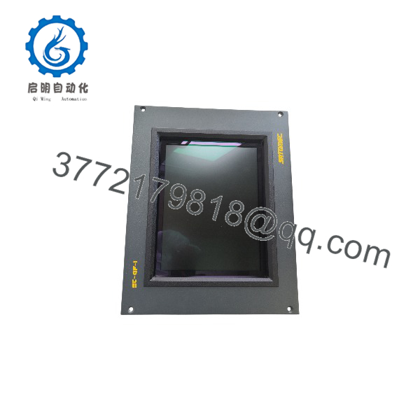
GF1-10TVD-102
GF1-10TVD-102
Troubleshooting Quick Reference
| Symptom | Possible Cause | Relevance to This Part | Quick Check Method | Recommendation |
|---|---|---|---|---|
| No display or startup LEDs | Missing 24 V DC, reversed polarity, blown fuse, or failed power circuit | ✅ High | Measure 20.4–28.8 V DC directly at the HMI power plug and verify +24 V, PE, and 0 V terminals | Check the supply, fuse, terminal wiring, and cabinet ground before replacing the HMI |
| Panel repeatedly reboots | Voltage drop, excessive ripple, insufficient supply capacity, or internal power fault | ✅ High | Monitor voltage at the panel during startup and backlight operation; check for drops below 20.4 V DC | Correct the power circuit before condemning the panel |
| Display powers but shows no application | Missing PCMCIA project card, corrupted project, or incorrect runtime configuration | ✅ High | Confirm the ATA Flash card is present and inspect the startup message | Preserve the original card and project before attempting a reload |
| Touch does not respond | Dirty infrared frame, blocked optical channel, failed touch controller, or damaged front panel | ✅ High | Clean the PMMA front frame with a soft damp cloth and observe the touch/status LEDs | Do not use solvents; retest after cleaning before replacing the panel |
| Touch areas are inaccurate | Touch calibration loss, damaged infrared channels, or incorrect screen configuration | ✅ Medium | Run the approved calibration routine and test the full screen grid | Replace or repair the touch assembly if calibration cannot be completed |
| Touch fault LED remains on | Touch-controller communication failure or defective infrared hardware | ✅ High | Check the touch status indicators during startup and inspect the front frame for obstruction | A persistent communication fault usually requires repair or panel replacement |
| PLC data is missing | Wrong communication board, project mismatch, cable fault, or incorrect controller parameters | ✅ High | Check the installed Slot 1 communication card and test the system port with the approved cable | Verify the project, card, cable, and PLC settings before replacing the display |
| Project will not transfer | Wrong GALILEO version, incorrect cable, incompatible PC Card, or failed system port | ✅ High | Record the existing runtime version and test the transfer path with a known-good card or cable | Back up the original project and use the documented Micro Innovation transfer method |
| HMI operates but field communication is unstable | Shielding, grounding, connector, or equipotential-bonding problem | ✅ Medium | Inspect metal-shell D-sub connectors and measure communication behavior with shield continuity verified | Use shielded copper communication cable and correct the cabinet bonding arrangement |
| Screen has dead pixels or lines | Aging LCD, impact damage, heat exposure, or internal ribbon fault | ✅ High | Display a full-screen test pattern and inspect all pixels and vertical/horizontal lines | Request a tested replacement with a documented LCD test |
| Front panel loses its seal | Damaged gasket, incorrect cutout, loose M5 fasteners, or missing compression frame | ✅ Medium | Inspect the gasket and verify the approximately 316 × 244 mm cutout | Replace the seal or mounting hardware before returning the panel to service |
| Communication card removed or inserted live | ESD damage or backplane fault | ✅ High | Check whether the card was changed with power applied and inspect for new startup faults | Power down fully and use ESD protection; use only approved Micro Innovation cards |
Important: The GF1-10TVD-102 is not a generic 24 V touchscreen. Its project, runtime, PCMCIA card, system port, and optional communication hardware are part of the replacement decision. Contact technical support with the complete label, front/rear photographs, GALILEO project version, PC Card details, supply measurements, and communication diagnostics if the fault remains unresolved.
Frequently Asked Questions
What is the Micro Innovation -102?
It is a GF-1 Micro Panel industrial HMI/operator interface for machine and process control. It provides color visualization, touch-based operator input, alarms, parameter entry, and communication with the automation system.
What display and power specifications apply?
The family documentation identifies a 10.4-inch TFT color LCD, 640 × 480 VGA resolution, and electrically isolated 24 V DC power. The effective DC input range is listed as 20.4–28.8 V DC.
Which software is used to program it?
The GF-1 platform uses Micro Innovation’s GALILEO engineering environment and GRS Runtime System. Recover the original project and verify the GALILEO version before attempting a replacement or project transfer.
How is the project stored?
Project images are stored on a PCMCIA/PC Card in Slot 0, using ATA Flash cards up to 64 MB according to the available GF-1 documentation. The card should be secured with the supplied pressure piece, especially when the panel is installed vertically.
Does the -102 have Ethernet or CAN?
Do not assume that it does. Some reseller pages attribute Ethernet, CAN, MODBUS, and other interfaces to this model, but those specifications conflict with the stronger GF-1 documentation. Confirm the installed communication expansion card and the rear-panel connectors on the actual unit.
Can I hot-swap a communication card?
No. Power must be removed before inserting or removing GF-1 communication hardware, and ESD precautions are required. The documentation also specifies Micro Innovation original communication boards for the expansion slot.
still supported?
It is treated as legacy/discontinued hardware in current industrial replacement records. Plan around tested surplus stock, repair availability, project preservation, and a controlled migration path rather than assuming normal OEM replacement support.
What condition should the listing state?
The seller should identify New Original, New Surplus, or Refurbished and tested. For a used panel, request a full power-up video, touch-grid test, LCD test pattern, RS-232/system-port test, PCMCIA-card test, communication-card details, and warranty terms.



