
 WhatsApp: +86 16626708626
 Email:
  Phone: +86 16626708626
Description
Key Technical Specifications
- Manufacturer Marking: Millipore or Tylan General, depending on label revision
- Model: CMHT-11S02
- Common Variant: CMHT-11S02-EMC
- Product Type: Capacitance manometer / vacuum pressure transducer
- Pressure Range: 0–10 Torr absolute
- Output Signal: 0–10 V DC analog output
- Measurement Principle: Capacitance diaphragm pressure sensing
- Primary Service: Vacuum-process pressure measurement and closed-loop control
- Typical Integration: Semiconductor process equipment, vacuum systems, deposition tools, etch systems, and gas-handling skids
- OEM Cross-Reference: LAM Research 853-011054-001 is associated with a CMHT-11S02 listing; verify against the physical label before using it as a substitute
- Electrical Interface: Verify connector type, pinout, supply requirement, and analog-output reference from the exact sensor label and equipment schematic
- Mechanical Interface: Verify vacuum fitting type, seal material, orientation, and allowable process-media compatibility before installation
- Calibration Requirement: Verify zero, span, accuracy, and calibration status before using the device for process-critical control
Supplier records consistently identify the CMHT-11S02-EMC as a 0–10 Torr manometer with a 0–10 V DC output. Listings also associate CMHT-11S02 with Tylan General and a LAM Research cross-reference, but these identifiers must be confirmed against the actual unit label.
Product Introduction
The Millipore CMHT-11S02 is a capacitance diaphragm manometer for absolute-pressure measurement in vacuum process equipment. The -EMC variant is identified as a 0–10 Torr device with a proportional 0–10 V DC analog output, allowing direct connection to an analog input, vacuum controller, or machine-control system.
This instrument is selected when an existing vacuum tool requires the same full-scale range, electrical output, connector arrangement, and vacuum fitting. A 10 Torr sensor is not interchangeable with a 1 Torr, 100 Torr, or different-output model without revising PLC scaling, control limits, calibration procedures, and process recipes.
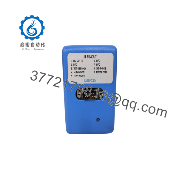
CMHT-11S02
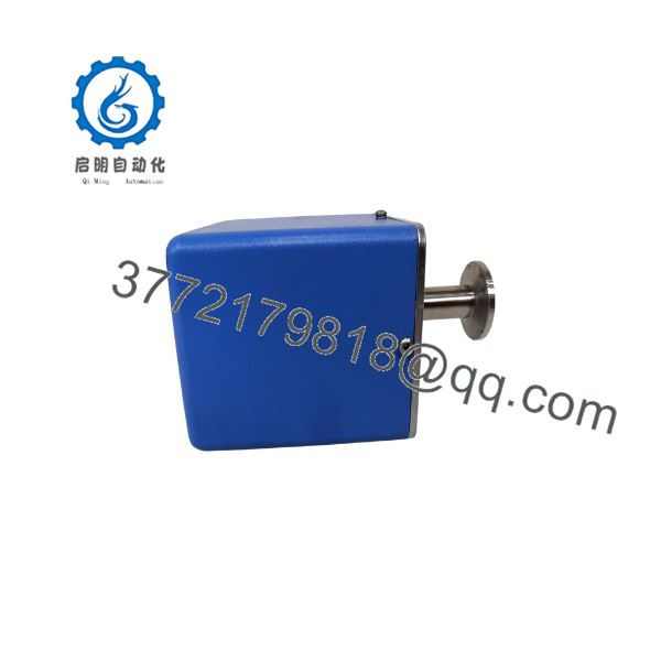
CMHT-11S02
Installation & Configuration Guide
Stage 1: Pre-Installation Preparation — 10 minutes
- ⚠️ Safety first: Notify operations, stop the vacuum process, isolate gas sources, and place the chamber or vacuum line in an approved safe condition. Apply lockout/tagout to the sensor power supply and related valve-control circuits.
- Verify the installed device label reads or and confirm the pressure range is 0–10 Torr.
- Confirm the replacement’s:
- Full-scale pressure range
- 0–10 V DC analog output
- Electrical connector type and pinout
- Vacuum-port fitting and seal arrangement
- Wetted-material compatibility
- Calibration label and date
- Prepare:
- Grounded ESD wrist strap
- Clean nitrile gloves
- Digital multimeter
- Approved vacuum-compatible wrench
- Clean lint-free wipes
- Correct replacement gasket, O-ring, or metal seal
- Smartphone for photographs
- Record the existing PLC or controller scaling. For a linear 0–10 V output over 0–10 Torr, the nominal relationship is:
PTorr=VoutputP_{Torr} = V_{output}
This relationship must still be verified against the actual model documentation and calibration label before returning the system to production.
- Photograph connector orientation, cable shielding, vacuum-port orientation, and any installed thermal or mechanical support.
⚠️ Critical: Do not touch the vacuum sealing surface, diaphragm area, or internal port with bare hands or tools. Contamination can create leaks, zero drift, or process contamination.
Stage 2: Removing the Old Sensor — 5 to 15 minutes
- Verify that the chamber or process line is vented or isolated according to the approved equipment procedure.
- Confirm there is no trapped pressure or hazardous process gas at the sensor connection.
- Disconnect sensor power and analog output at the connector. Label the cable before removal.
- Remove any strain-relief clamp or support bracket.
- Hold the sensor body with the correct wrench and loosen the vacuum connection carefully.
- Remove the sensor without applying side load to the fitting or bending the process line.
- Immediately cover the open vacuum line with an approved clean cap or protective cover.
- Inspect the removed seal, flange, gasket face, and cable connector for contamination, corrosion, loose pins, or damage.
⚠️ Note: Keep the old manometer until the replacement passes leak checking, electrical verification, zero confirmation, and process-control validation.
Stage 3: Installing the New Sensor — 10 minutes
- Wear clean gloves. Remove the replacement sensor from its packaging only when the vacuum connection is ready.
- Verify the pressure range, output specification, connector, and fitting against the old device.
- Install a new compatible gasket, O-ring, or metal seal. Do not reuse a damaged or compressed vacuum seal.
- Align the sensor so the electrical connector is accessible and the cable will not impose force on the sensor body.
- Tighten the vacuum fitting to the equipment manufacturer’s approved torque specification. Do not overtighten fittings; distorted seals and damaged threads create slow leaks that are difficult to diagnose.
- Reconnect the cable, following the photographed orientation and pin identification.
- Restore cable shielding exactly as installed. Improper shield grounding can inject noise into the 0–10 V signal.
- Confirm the sensor is supported where required and that no pipe load acts on the housing.
Self-checklist:
- Model and 10 Torr range match
- 0–10 V DC output requirement matches
- Vacuum fitting and seal type match
- New clean seal installed
- Connector is fully latched
- Cable shielding is restored
- No mechanical stress is applied to the sensor
Stage 4: Power-On and Testing — 15 to 30 minutes
- Before reconnecting to the controller, verify the supply voltage and analog-input wiring against the equipment schematic.
- Energize the sensor and allow the recommended stabilization time specified by the equipment or sensor documentation.
- Measure the analog output with a high-impedance multimeter.
- At a known reference condition, verify that the output is credible for the actual vacuum level. Do not use atmosphere as a reference if the sensor range is 0–10 Torr; atmospheric pressure exceeds the specified range by a large margin.
- Pump the chamber down under controlled conditions and compare sensor output with a calibrated reference gauge within the relevant pressure range.
- Confirm PLC scaling, display scaling, alarm thresholds, interlocks, and recipe limits.
- Perform a leak check at the replaced connection using the plant-approved method.
- Return the system to process only after pressure indications are stable and the control system accepts the signal.
⚠️ Troubleshooting note: If the PLC reads 0 Torr or a fixed high value, check supply voltage, connector pinout, analog common, cable damage, and input scaling before declaring the sensor failed. If the reading drifts after installation, inspect for a leak, contamination, thermal instability, or an incompatible grounding arrangement.
Frequently Asked Questions
Is a pressure switch?
No. It is identified as a capacitance manometer, which is an analog absolute-pressure measurement device. The -EMC is listed with a 0–10 V DC output across a 0–10 Torr pressure range. Your PLC, vacuum controller, or tool controller uses that analog signal to display pressure, generate alarms, or regulate a vacuum process.
Can I replace a 10 Torr with a different pressure range?
Not as a direct replacement. A sensor with a different full-scale range changes the relationship between pressure and analog voltage, which can make PLC values, alarm limits, recipe thresholds, and closed-loop control incorrect. For example, replacing a 10 Torr device with a 100 Torr version while retaining the same scaling could make the control system report 1 Torr when the actual pressure is 10 Torr.
Can I install this sensor under atmospheric pressure?
Do not assume that you can. A 0–10 Torr sensor is designed for a low-pressure measurement range, while atmospheric pressure is roughly 760 Torr. Verify the sensor’s allowable overpressure rating from the OEM documentation or exact label before exposing it to atmosphere. If the equipment procedure requires venting, follow that procedure; do not use generic assumptions for a legacy vacuum sensor.
Is obsolete, and is new stock still available?
It is a legacy vacuum-process component, and stock usually comes from New Surplus, used tested, or refurbished sources. Supplier listings show limited availability for and -EMC variants, but availability changes quickly. Request current photos, the exact full label, calibration information, connector photographs, and confirmation of the 0–10 Torr range before purchasing.
Does the sensor need calibration after replacement?
For process-critical use, yes. Verify zero and span against a calibrated reference over the operating range that matters to the tool. Even if the output is electrically correct, a drifted capacitance manometer can cause incorrect gas-flow control, endpoint decisions, deposition results, or vacuum interlock behavior.
Why does the replacement sensor show a voltage but the machine still alarms?
The machine may be using an alarm threshold, signal-quality check, scaling coefficient, or interlock that does not match the replacement’s output. Verify the PLC or tool-controller analog scaling, signal common, configured engineering range, and alarm limits. Also verify that the sensor output is stable and that the chamber is actually reaching the required pressure.
Why is the price lower than an OEM replacement quote?
New Surplus material may originate from unused service stock, decommissioned tool inventory, or distributor excess inventory. The lower price can reflect legacy status, uncertain calibration history, or limited manufacturer support. For a process-critical sensor, ask for a defined condition statement, test evidence, calibration traceability if available, warranty terms, and the right to reject a unit that does not match the quoted model and range.



