
 WhatsApp: +86 16626708626
 Email:
  Phone: +86 16626708626
Description
Key Technical Specifications
| Parameter | Value |
|---|---|
| Manufacturer | Mitsubishi Electric |
| Model | A1S61PN |
| Product Type | PLC power supply unit |
| Series | MELSEC-A / AnS Series |
| Mounting Position | Power-supply slot on compatible AnS base unit |
| Input Voltage | 100–240 V AC, −15% to +10% |
| Input Frequency | 50/60 Hz, ±5% |
| Input Voltage Distortion | Within 5% |
| Maximum Apparent Power | 105 VA |
| Inrush Current | Within 20 A for 8 ms |
| Rated Output Voltage | 5 V DC |
| Rated Output Current | 5 A |
| Overcurrent Protection | 5.5 A or more |
| Overvoltage Protection | 5.5–6.5 V DC |
| Efficiency | 65% or more |
| Momentary Power Interruption | Within 20 ms |
| Dielectric Withstand | 2,300 V AC for 1 minute between input/LG and output/FG groups |
| Insulation Resistance | 10 MΩ or more at 500 V DC |
| External Wiring | M3.5 screw terminal block |
| Power Indication | Power LED |
| Dimensions, H × W × D | 130 × 55 × 94 mm |
| Weight | Approximately 0.60 kg |
Mitsubishi identifies A1S61PN as a MELSEC-A AnS-series PLC power supply with a 5 V DC, 5 A output. Its manuals also state that A1S61PN uses a 100–240 V AC wide-range input and that the LG and FG terminals must be shorted together and grounded where the applicable installation requirements call for it.
Product Introduction
The Mitsubishi Electric A1S61PN is a rack-mounted power supply unit for MELSEC-A and AnS-series PLC systems. It accepts 100–240 V AC input power and supplies regulated 5 V DC power to the compatible base unit and installed PLC modules. It mounts in the dedicated power-supply position of an AnS base or supported extension base.
The A1S61PN is used when a legacy A/AnS rack needs an exact 5 V DC, 5 A replacement without changing the base, CPU, or I/O arrangement. Confirm the existing base-unit model, installed module load, supply slot, grounding method, and local electrical requirements before ordering or energizing the replacement.
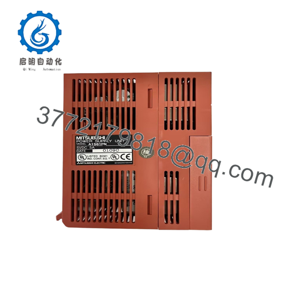
A1S61PN
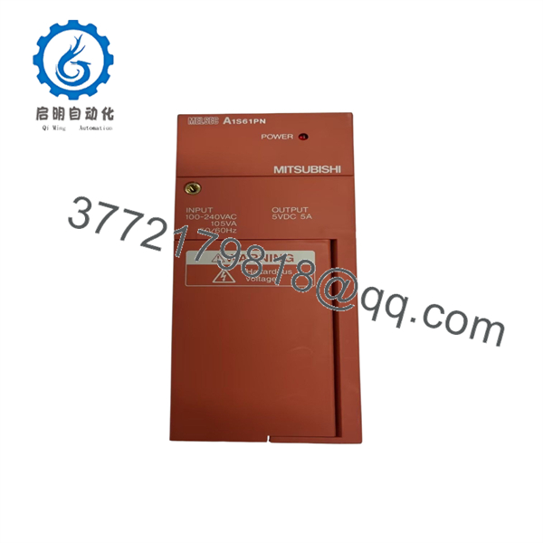
A1S61PN
Troubleshooting Quick Reference
| Symptom | Possible Cause | Relevance to This Part | Quick Check Method | Recommendation |
|---|---|---|---|---|
| Power LED is off | Missing AC input, upstream breaker open, blown fuse, loose terminal, failed PSU | ✅ High | Measure 100–240 V AC at the A1S61PN input terminals using a properly rated meter and the approved wiring drawing | Restore incoming power before replacing the PSU |
| Power LED is on but PLC CPU does not run | Overloaded 5 V DC rail, failed CPU, base-unit backplane issue, loose module, failed PSU output | ⚠️ Medium | Measure 5 V DC at approved base-unit test points and check CPU LEDs, module seating, and diagnostic indicators | Check rack load and CPU condition before replacing the supply |
| PLC restarts intermittently | Supply voltage sag, overloaded rack, poor terminal connection, weak upstream source, aged PSU | ✅ High | Trend the 5 V DC rail during startup and peak load; inspect M3.5 terminal torque and AC feeder condition | Correct input or load issue; replace the PSU if output regulation is unstable |
| PLC fails after adding modules | Total 5 V DC current exceeds 5 A, excessive inrush, incorrect system load calculation | ⚠️ Medium | Add the 5 V DC current consumption of every installed CPU, I/O, communication, and special-function module | Reduce the rack load or redesign the power arrangement before replacing the PSU |
| No output after a short circuit | Downstream short, failed I/O module, damaged backplane, overcurrent protection active, failed supply | ✅ High | Isolate downstream modules one at a time under approved procedures and inspect for damaged components or shorts | Find the downstream fault before installing another |
| Random analog noise or communication faults | Poor grounding, LG/FG not correctly bonded, noisy AC feed, power wiring routed near VFD output cables | ❌ Usually Low | Inspect ground connection, cabinet bonding, AC routing, and separation from high-current or VFD cables | Correct installation and grounding before replacing the power supply |
| Supply runs hot or cabinet is warm | Overload, restricted airflow, high cabinet ambient temperature, aged components | ⚠️ Medium | Check cabinet temperature, ventilation, module loading, and discoloration around power terminals | Improve cooling and confirm load margin; replace if supply shows abnormal heating |
| Replacement supply does not fit or seat | Wrong series PSU, incompatible base unit, damaged slot guides, incorrect mounting position | ✅ High | Compare the original label, base-unit model, mounting dimensions, and connector location | Confirm AnS compatibility before forcing installation |
Field warning: A dead PLC rack does not automatically mean a bad . Check the incoming AC supply, feeder fuse, terminal tightness, rack loading, and downstream modules first. A shorted I/O card or overloaded 5 V DC bus can shut down the supply and make a healthy PSU look defective.
❗ Verify the 5 V load budget: The provides a rated 5 V DC output of 5 A. Add the specified 5 V current consumption of the CPU and every installed module, then leave operating margin. Do not size the rack by guesswork. A PSU operating at its limit may run warm, reset during inrush events, or fail early.
❗ LG and FG grounding matters: Mitsubishi documentation calls for shorting LG and FG terminals and grounding them for the applicable installation. Do not ignore this detail. Poor grounding can increase noise sensitivity and create intermittent behavior that gets misdiagnosed as a PLC or I/O fault.
❗ Do not confuse this with a positioning module: One third-party listing incorrectly calls a high-speed positioning module. Mitsubishi documentation and official product information identify it as an AnS-series power supply. Do not connect pulse outputs, servo wiring, or field I/O signals to it.
❗ Wide-range input does not eliminate electrical checks: supports a 100–240 V AC input range, but you still must verify feeder voltage, frequency, polarity where applicable, fusing, isolation, and local panel standards. An unstable feeder, weak control transformer, or loose M3.5 terminal can still create rack resets.
❗ Photograph wiring before removal: Take a clear photo of the AC input, LG/FG bonding, ground conductor, feeder label, terminal layout, and rack position. It is the most common rookie mistake, but it happens constantly. Take a picture before you touch anything. Seriously.
❗ ESD and electrical safety: Use approved lockout/tagout procedures before removing the supply. Verify absence of hazardous voltage with a properly rated meter. Wear ESD protection while handling the PLC rack and adjacent modules.
Keep these checks in mind and you will save yourself 90% of typical rework time. If you are stuck, send technical support photos of the PSU label, base-unit model, module arrangement, power LED status, AC input measurement, 5 V DC measurement, and CPU diagnostic LEDs.
Frequently Asked Questions
What is Mitsubishi ?
The Mitsubishi Electric is a MELSEC-A / AnS-series PLC power supply unit. It mounts in the power-supply slot of a compatible base unit and provides a rated 5 V DC output for the PLC rack and installed modules.
What input voltage does accept?
accepts 100–240 V AC, with an allowable range of −15% to +10%, at 50/60 Hz ±5%. Mitsubishi documentation states that the does not require manual switching across its 100–240 V AC wide input range.
What output does provide?
The rated output is 5 V DC at 5 A. The listed maximum apparent input power is 105 VA, with overcurrent protection specified at 5.5 A or more and overvoltage protection in the 5.5–6.5 V DC range.
Is compatible with every MELSEC-A PLC base?
No. It is an AnS-series power supply and must be installed in a compatible power-supply slot. Mitsubishi identifies it as compatible with LA1S extension base arrangements and lists it within the AnS-series power-supply family. Verify the exact base-unit model and extension architecture before ordering.
Can I hot-swap the ?
No. Do not hot-swap this mains-powered PLC power supply. Removing it live can interrupt every module in the rack, corrupt a running process, damage connectors, and expose personnel to hazardous voltage. Use the approved shutdown, lockout/tagout, discharge, and restart procedure.
Why does my PLC restart after I add an I/O module?
The most likely causes are an overloaded 5 V DC power budget, increased inrush current, a loose base connection, or a failing module. Calculate the total 5 V DC draw of all installed modules and compare it with the ’s 5 A rating. Check the new module and its seating before replacing the power supply.
Do I need to connect LG and FG?
Mitsubishi documentation instructs users to short LG and FG terminals and ground them for installations subject to the applicable safety and noise-filter requirements. Follow the exact manual and your site’s grounding standard. Do not use the ground connection as a substitute for a DC signal common.
Is obsolete?
Treat as a legacy MELSEC-A / AnS power-supply spare. It remains visible through Mitsubishi channels and independent suppliers, but lifecycle status, regional availability, and replacement strategy should be confirmed for your market and installed system. If long-term support is required, plan a staged migration rather than relying on a single surplus spare.
Why is a New Surplus less expensive than factory inventory?
New Surplus inventory commonly comes from unused maintenance stores, cancelled projects, system upgrades, or warehouse liquidation. It may be unused but not factory sealed. Because it is a power supply, storage age matters. Request label photos, date-code information, housing and terminal-condition photos, output-load test evidence, packing photos, warranty terms, and a return process.
What test process should a supplier provide?
For a Mitsubishi power supply, request a documented test process for the exact unit:
- Verify the label, serial information, and visible revision markings
- Inspect the enclosure, mounting latch, base connector, M3.5 terminals, power LED, and ground terminals
- Check for corrosion, cracked plastic, overheated terminals, rework marks, contamination, and damaged labels
- Apply a controlled 100–240 V AC input in a safe test fixture
- Verify stable 5 V DC output at no load and under a representative controlled load
- Confirm overcurrent and output-regulation behavior only within an approved test procedure
- Run the unit long enough to identify unstable output, abnormal heating, noise, or intermittent LED behavior
- Confirm proper LG/FG terminal condition and protective-earth continuity
- Provide a test report with input voltage, load current, measured output voltage, run duration, and observed condition
- Package in antistatic protection with terminal protection, foam support, heavy-duty boxing, QC sign-off, and written warranty terms
Test photos and video should be available upon request. A power LED alone does not prove the unit can maintain a regulated 5 V DC rail under rack load.



