
 WhatsApp: +86 16626708626
 Email:
  Phone: +86 16626708626
Description
Key Technical Specifications
| Parameter | Specification |
| Product Model | MR-J2M-20DU |
| Manufacturer | Mitsubishi Electric |
| Control System | MELSERVO-J2-Multi Series |
| Rated Output Capacity | 200 W (0.2 kW) |
| Compatible Servo Motors | HC-MFS23, HC-KFS23 |
| Power Supply Input | DC bus feed from MR-J2M-PBU Power Unit |
| Output Voltage / Current | 3-Phase 170 V AC, 1.5 A |
| Control Method | Sinusoidal PWM control / current control system |
| Speed Frequency Response | 250 Hz or higher |
| Operating Temperature | 0 to +55 °C (32 to 131 °F) non-condensing |
| Cooling Method | Natural convection / heat sink dissipation |
| Weight | 0.6 kg (1.32 lbs) |
Product Introduction
The Mitsubishi MR-J2M-20DU is a 200W multi-axis servo drive unit designed for the MELSERVO-J2-Multi platform. Operating as an individual axis drive module connected via a shared DC bus to a central MR-J2M-PBU power supply unit, it eliminates individual AC power cabling per axis, making it ideal for compact multi-axis machinery like pick-and-place robots, packaging lines, and semiconductor processing equipment.
By offloading the main power rectification to the central power unit, the MR-J2M-20DU maintains a narrow physical footprint while offering precise torque, speed, and position control. It communicates directly with Mitsubishi motion controllers or host PLC systems, delivering fast loop response times and support for high-resolution encoder feedback.
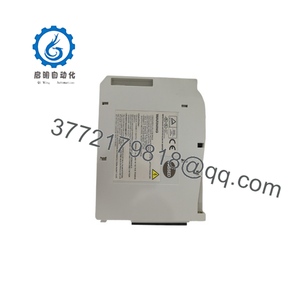
MR-J2M-20DU
MR-J2M-20DU
Installation & Configuration Guide
Stage 1: Pre-Installation Preparation (Estimated Time: 10 Minutes)
- ⚠️ Safety First: Disconnect all main AC line power to the MR-J2M-PBU power supply unit. Wait at least 10 minutes for the internal DC bus capacitors to discharge down to safe levels (below 50 V DC). Verify zero voltage across the P(+) and N(-) busbars with a multimeter.
- Tools Required: ESD wrist strap, PH1/PH2 screwdrivers, Fluke digital multimeter, wire marker labels, smartphone.
- Data Backup: Document parameter configurations in MR Configurator software or write down custom parameter changes from the motion controller setup. Photograph all front-panel rotary switches and DIP switches.
Stage 2: Removing the Old Module (Estimated Time: 10 Minutes)
- Detach front-facing control signal connectors (CN1A, CN1B, CN2) by pinching the side locking tabs. Do not pull on the wiring harness.
- Unbolt the top and bottom DC busbar connection screws bridging the drive unit to the adjacent power or drive units.
- Remove the upper and lower mounting screws securing the MR-J2M-20DU chassis to the backplane DIN/panel frame.
- Carefully slide the module forward off the rack, keeping it straight to prevent binding on adjacent modules.
- ⚠️ Note: Inspect the exposed DC bus interface for arc oxidation, dust accumulation, or thermal damage before staging the replacement.
Stage 3: Installing the New Module (Estimated Time: 10 Minutes)
- Put on an ESD wrist strap grounded to the panel enclosure. Verify the part number matches MR-J2M-20DU.
- Configuration Clone: Set the rotary station number switch on the front panel to mirror the exact node address of the removed module.
- Mount the drive unit onto the panel backplate and tighten the mounting screws to 1.2 N·m.
- Reinstall the DC busbar bridging plates between P(+) and N(-) terminals. Torque power terminals firmly to 1.5 N·m to prevent high-resistance hot spots.
- Reconnect encoder (CN2) and communication/control (CN1A/CN1B) connectors until they lock into place.
- Self-Checklist: [ ] Axis rotary switch matches original, [ ] DC busbars torqued tightly, [ ] Encoder and comm cables clicked shut.
Stage 4: Power-On & Testing (Estimated Time: 10 Minutes)
- Perform a resistance test between P(+) and N(-) to ensure no short circuits exist across the bus.
- Apply control power to the central power unit first.
- Observe the LED status indicator on the MR-J2M-20DU. A steady display indicates normal standby state.
- If an error code appears (e.g., Alarm 16, Alarm 20), check encoder seating and bus voltage.
- Perform a low-speed jog test from the host motion controller to verify rotation direction and encoder feedback stability before handing over to operations.
- Frequently Asked Questions (FAQ)
Can I hot-swap the MR- while the main DC bus is energized?
No. Never attempt to remove or plug in an MR- unit while the DC bus is live. Multi-axis systems share a common 300 V DC bus fed from the MR-J2M-PBU power unit. Hot-plugging will create heavy electrical arcing across the busbar terminals, damaging the internal drive power electronics and risking serious personal injury.
Since the MR-J2M series is mature, are these units genuinely original and operational?
Yes. Our inventory consists of fully verified, new surplus and fully tested industrial stock. Every unit undergoes a complete visual, electrical, and functional inspection protocol—including continuous 24-hour load testing on a genuine Mitsubishi rack with an HC-MFS series motor—before entering inventory.
Will I lose my drive parameter configuration when I swap the drive unit?
In most multi-axis setups using MR-J2M drive units, the operational parameters (such as electronic gear ratios, speed limits, and positioning parameters) are stored in and transferred from the central motion controller or PLC upon boot. However, you must manually set the physical rotary node selection switch on the front panel of the new module so the controller recognizes it on the bus.
What is the primary cause of sudden failure on these drives during startup?
The single most common mistake is loose hardware on the DC busbars. If the screws connecting the P(+) and N(-) copper bars are not torqued down correctly, high contact resistance under motor acceleration generates localized heat, tripping the drive on undervoltage or overcurrent alarms. Always torque busbar screws to 1.5 N·m.
Why is your pricing for new surplus MR- units lower than original factory list prices?
Because Mitsubishi phased out the MR-J2M series in favor of newer platforms like MR-J3/MR-J4, official factory pricing reflects legacy production overhead. We source directly from plant overstock, machine builder spares, and verified surplus channels, allowing us to supply genuine OEM hardware without the lead times or markup of factory special orders.



