 WhatsApp: +86 16626708626
 Email:
 Phone: +86 16626708626
Description
Core Product Summary (Brand / Model / Key Attributes)
The Mitsubishi PM-60MR is a compact programmable logic controller (PLC) main unit belonging to the MELSEC FX micro PLC family architecture, designed for standalone machine control and distributed industrial automation applications. The controller integrates the central processing unit, power supply, and fixed digital input/output hardware into a single base block, serving as the central logic supervisor for small-to-medium machinery, packaging equipment, and process sub-systems.
Operating on a standard 100–240 V AC power line, the Mitsubishi PM-60MR features a total fixed density of 60 I/O points, configured as 36 digital inputs (24 V DC sinking/sourcing) and 24 electromechanical relay outputs. System configuration and program monitoring are accessed through a front-panel 8-pin mini-DIN RS-422 communications port using standard programming cables and software. Internal execution relies on built-in EEPROM program memory, backed by integrated terminal strips for field wiring and status LEDs for real-time diagnostics.
Key Technical Specifications
| Parameter | Specification Details |
| Product Type | Programmable Logic Controller (PLC) Main CPU Base Unit |
| Product Family | MELSEC FX Micro PLC Architecture |
| Total I/O Capacity | 60 points fixed on base unit |
| Digital Inputs | 36 points (24 V DC, 7 mA nominal, sinking/sourcing) |
| Digital Outputs | 24 points (Electromechanical Relay) |
| Supply Voltage | 100–240 V AC (+10% / -15%), 50/60 Hz |
| Auxiliary Service Power | 24 V DC, 250 mA sensor supply output |
| Output Switching Capacity | 2 A per point / 8 A per common (250 V AC / 30 V DC resistive) |
| Mechanical Life (Relay) | 3 \times 10^6 operations minimum |
| Electrical Life (Relay) | 100,000 operations at rated resistive load |
| Program Memory | 2,000 steps internal EEPROM (expandable via cassette) |
| Instruction Execution Speed | 0.7 µs/step (basic instructions), 1.5 µs/step (applied instructions) |
| Programming Interface | 8-pin mini-DIN connector (RS-422 signal level) |
| Input Response / Filter | 10 ms default digital filter (adjustable via system registers) |
Detailed Product Overview
The Mitsubishi PM-60MR functions as an self-contained automation controller, combining power conversion, logic processing, and physical I/O signal conditioning inside one physical casing. Built upon Mitsubishi Electric’s established micro-PLC engineering standards, the unit decodes binary field signals from switches, photoelectric sensors, and limit sensors, processing them according to user-programmed ladder logic instructions to trigger output devices such as contactors, solenoid valves, and indicator lamps.
The integrated 36 digital inputs utilize 24 V DC optical isolation to protect internal control circuitry from field electrical noise and voltage spikes. The input terminals support both sinking (NPN) and sourcing (PNP) wiring arrangements, providing adaptation to various industrial sensor types. An onboard 24 V DC service power supply allows low-current sensors to be powered directly from the controller base, simplifying enclosure wiring layout.
The 24 relay outputs offer potential-free contacts capable of switching loads up to 2 A per point across AC and DC operational voltages. Relay isolation enables direct drive of external inductive loads without requiring interposing relays, provided external surge protection is installed. Logic routines reside on non-volatile internal memory, preventing program loss during extended power outages.
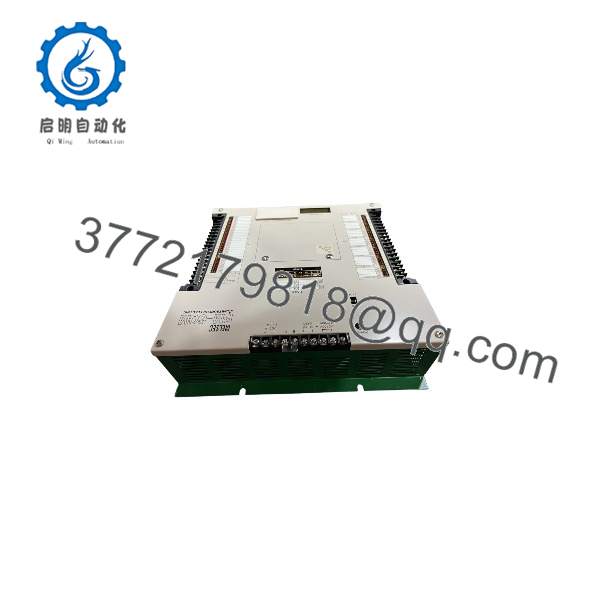
PM-60MR
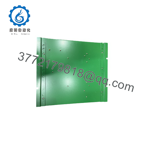
PM-60MR
System Compatibility & Integration Requirements
| Item / Dependency | Verified Compatibility or Requirement | Practical Note |
| System Architecture | MELSEC FX Series Instruction Set | Programmed via standard FX-compatible programming packages. |
| Programming Hardware | SC-09 or FX-USB-AW converter cable | Connects 8-pin mini-DIN port on PLC faceplate to PC serial/USB port. |
| Software Support | GX Developer, GX Works2 (FXCPU / FX0N target setting) | Target PLC selection configured to FX0N CPU class in software setup. |
| Handheld Terminals | FX-20P-E handheld programming unit | Requires FX-20P-CAB connection cable for direct programming access. |
| Power Connections | Screw terminal block (L, N terminals) | Requires line fuse protection on incoming AC power lines. |
| Terminal Blocks | Barrier-style terminal strip with protective cover | Uses ring or spade crimp lugs for secure field conductor connections. |
Dimensions, Mounting & Connection Notes
- Mounting Options: Designed for direct cabinet backpanel mounting using mounting screw holes or snap-on mounting on standard 35 mm DIN rail.
- Wiring Lugs: Field connections feature barrier screw terminals; stranded wire should be fitted with insulated crimp terminals.
- Relay Protection: For inductive load control (solenoids, contactor coils), install external RC snubbers across AC loads or flyback diodes across DC loads to extend relay contact service life.
- Grounding Requirements: Dedicated S/S and frame ground (FG) terminals must be bonded to a clean earth ground to maintain noise immunity in high-interference environments.
- Thermal Clearances: Allow minimum 50 mm clearance above and below the base unit within the enclosure to ensure proper natural convection cooling.
Engineering Selection Highlights
- High-Density Base Configuration: Integrates 36 inputs and 24 outputs into a compact footprint, eliminating the need for add-on I/O modules in standard 60-point machinery applications.
- Universal AC Input Power: Accepts wide AC supply voltages (100–240 V AC), allowing direct integration into global control panels without dedicated step-down transformers.
- Flexible Sensor Compatibility: Bi-directional input hardware supports both NPN and PNP field devices without extra interface hardware.
- Isolated Dry-Contact Outputs: Relay contact outputs allow isolation between separate load voltage circuits (e.g., mixing 24 V DC control circuits and 120 V AC contactor coils).
- Integrated Sensor Power Auxiliary Supply: Provides onboard 24 V DC power for direct connection of field transmitters and sensors up to 250 mA total draw.
- Standard Industrial Communication Interface: Uses the standard MELSEC 8-pin mini-DIN serial interface for programming tool connection and operator interface access.
FAQ
What type of module is the Mitsubishi PM-60MR?
The PM-60MR is a 60-point compact programmable logic controller (PLC) main CPU base unit featuring 36 digital inputs and 24 relay outputs powered by an AC supply line.
What is the I/O point distribution on the PM-60MR base unit?
The base unit includes 36 digital inputs (24 V DC) and 24 electromechanical relay outputs.
What supply voltage is required to power the Mitsubishi PM-60MR?
The controller requires an incoming power line supply of 100–240 V AC at 50/60 Hz.
Which programming interface is built into the unit?
The unit features an 8-pin mini-DIN front-panel port utilizing RS-422 signal levels, compatible with SC-09 and FX-USB-AW programming cables.
Does the PM-60MR provide auxiliary sensor power?
Yes, the base unit supplies an onboard 24 V DC auxiliary output rated at 250 mA to power connected sensors and field inputs.
Which software packages program the Mitsubishi PM-60MR?
Programming is performed using standard Mitsubishi automation software like GX Developer or GX Works2, selecting the FX0N CPU series setting during project creation.
Verification & Troubleshooting Notes
- Power Indicator Off: Verify main incoming voltage across the L and N terminals (100–240 V AC). Inspect the internal primary power fuse if line voltage is confirmed present.
- ERROR LED Illumination / Flashing: Indicates program memory corruption, hardware fault, or syntax errors in ladder logic execution. Connect programming software to perform a diagnostic CPU check and verify program syntax.
- Input LED Not Lighting: Check voltage across the input terminal and 24V/COM line. Confirm input signal wiring aligns with sinking or sourcing (S/S) terminal configuration.
- Output LED Active but Load Inoperative: Verify external load power supply continuity and relay terminal output connections. Inspect relay contacts for wear or electrical damage if switching high inductive loads repeatedly.
- Communication Link Failure: Ensure the SC-09 or FX-USB-AW interface cable is firmly seated in the 8-pin mini-DIN port and correct COM port settings are assigned in GX Developer / GX Works2.