
 WhatsApp: +86 16626708626
 Email:
  Phone: +86 16626708626
Description
3. Key Technical Specifications
| Parameter | Specification / Value |
| Manufacturer | Modicon / Schneider Electric |
| Part Number | AS-B814-108 |
| Module Type | Discrete Relay Output Board |
| Number of Outputs | 16 Isolated Normally Open (NO) Contacts |
| Operating Voltage Range | 5 to 250 V AC / 5 to 30 V DC |
| Maximum Current per Point | 2.0 A continuous |
| Maximum Current per Module | 16.0 A total |
| Response Time (Off-to-On) | 10 ms maximum |
| Response Time (On-to-Off) | 10 ms maximum |
| Isolation Voltage | 1500 V RMS field-to-bus |
| Power Dissipation | 8.5 W maximum |
| Mounting Orientation | Standard 800 Series I/O Housing / Rack |
4. Product Introduction & Supply Chain Strategy
The Modicon AS-B814-108 is a heavy-duty 16-point relay output card engineered for 800 Series PLC architectures across water treatment, discrete manufacturing, and material handling applications. It provides galvanic isolation and physical relay switching for interlocks, motor starters, solenoid valves, and visual alarms operating at varying AC or DC signal levels.
Supplied strictly as Brand New Surplus, this module gives plant maintenance and supply chain teams an immediate insurance policy against extended OEM lead times and high list prices. Purchasing New Surplus avoids the severe operational hazards associated with used or refurbished cards—such as pitted contact points, degraded coil insulation, or intermittent backplane trace faults—ensuring your plant maintains maximum reliability and zero unscheduled downtime on mature PLC racks.
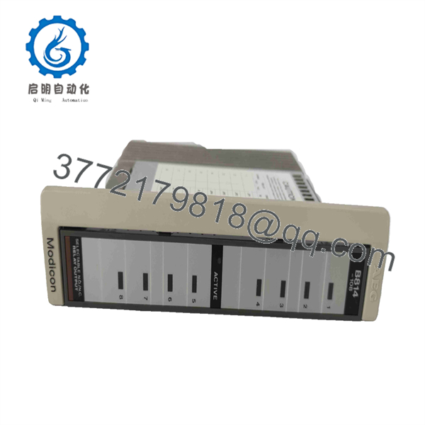
AS-B814-108
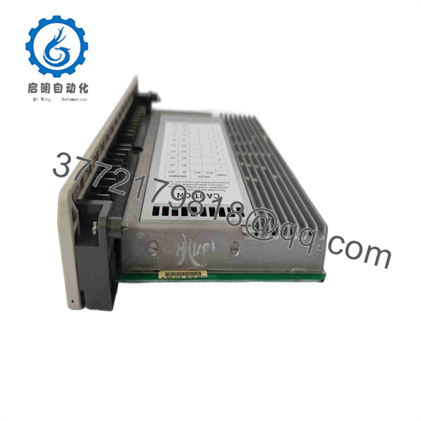
AS-B814-108
5. Installation & Configuration Guide
1.Stage 1: Pre-Installation (Prep & Safety):Safety Lockout & Site Prep.
Isolate all high-voltage line feeds powering the PLC rack and the field load circuits wired to the terminal block using full lock-out/tag-out (LOTO) procedures. Put on a grounded ESD wrist strap before handling sensitive hardware. Photograph all terminal wiring connections and keying pin configurations on the old AS-B814-108 module for setup verification.
Verification: Test field output terminal points with a calibrated multimeter to confirm zero potential before touching wiring arms.
2.Stage 2: Removal:Safe Card Extraction.
Loosen the top and bottom retaining screws on the module faceplate. Depress the terminal block release latches and swing the field wiring connector away from the front of the module without disturbing individual field wires. Smoothly pull the card straight out from the housing guides to avoid bending or damaging the backplane edge connector pins.
Verification: Visually inspect the backplane slot for debris, dust build-up, or mechanical pin damage.
3.Stage 3: Installation (Clone & Seat):Keying & Installation.
Verify that the mechanical keying pins on the rear of the new AS-B814-108 module match the slot position of the original card to prevent accidental cross-insertion of incorrect module types. Slide the new card evenly into the housing slot until the backplane connector seats firmly. Tighten top and bottom retaining screws, then snap the pre-wired terminal block back onto the module.
Verification: Confirm the terminal block latches fully engage on both sides of the front faceplate.
4.Stage 4: Power-On & Testing:Cold Checks & Boot Sequence.
Energize the main PLC rack power supply while leaving field load power disconnected. Observe the front panel LED diagnostic indicators during initial boot-up. Ensure the logic power indicator lights up solid and no fault LEDs remain latched. Execute a forced-output test cycle from the PLC software to verify relay coil actuation clicks across all 16 points before energizing field load power.
Verification: Confirm active output channel LEDs light up in sequence corresponding to PLC logic commands.
6. Firmware/Software Versions & Upgrade Notes
- Target Hardware Revision: Hardware Rev B / Rev C (Fully backplane-compatible with standard 800 Series backplane controllers).
- Cross-Compatibility Restrictions: The AS-B814-108 functions as a passive I/O slave card, making it independent of main CPU firmware builds. However, ensure the physical slot addressing in Modsoft / ProWORX 32 / EcoStruxure matches the module’s slot location precisely.
- Replacement Guidance: When replacing an older revision card with an AS-B814-108, always verify total current limits across the terminal block commons. Inductive field loads (solenoids, contactor coils) must have external RC suppressors or flyback diodes installed to prevent contact arcing and premature mechanical relay wear.
7. Frequently Asked Questions (FAQ)
Q: Is this Modicon AS- module original factory new, or refurbished?
A: This unit is 100% Brand New Surplus. It has never been deployed in an active production panel, never pulled from a decommissioned plant, and has zero repaired circuits or pitted relay contacts. It ships in original anti-static packaging with clean edge connectors.
Q: Why should we buy New Surplus instead of lower-cost refurbished boards?
A: Refurbished relay cards carry hidden wear from millions of electromechanical switching cycles. Contact points oxidize or pit over time, causing high resistance or stuck-closed faults. Paying a small premium for New Surplus guarantees fresh internal relay contacts, full operational longevity, and prevents expensive downtime events.
Q: Can I hot-swap the AS- while the PLC rack is powered ON?
A: No. Hot-swapping 800 Series I/O modules can cause electrical arcing across backplane pins, disrupt backplane bus communications, or trigger an immediate controller crash. Always disconnect rack power and field load voltage before inserting or removing the card.
Q: Do I need to program or configure jumpers on this board before installation?
A: The AS- is a hardware-configured discrete output card. It does not contain dip switches or programmable firmware. Address assignment is determined entirely by the card’s physical slot position in the 800 Series I/O rack.
Q: What is the warranty policy on this New Surplus board?
A: We back this AS- module with a comprehensive 1-year functional warranty from the delivery date. Every unit undergoes strict physical and electrical verification prior to dispatch.



