WhatsApp: +86 16626708626
 Email:
 Phone: +86 16626708626
Description
Key Technical Specifications
- Full Model: PC-E984-685R
- Controller Family: Modicon 984-680/685 slot-mount controllers
- CPU: 984 processor, logic solve speed ~1 ms/K (per Radwell catalog data: “1 Logic Solve Speed MS/K”)
- User Memory: 16K (user-changeable executive and user memory on plug-in daughter boards/PROMs)
- Data Memory: 10K
- Discrete I/O: Up to 2,048 points (984-685 class, via local I/O and S908 Remote I/O)
- Analog I/O: Supports up to 1,920 analog points in 16-bit words (984-680/685 system)
- Rack Support: Controls up to 4 racks (1 primary H819 housing + expansion)
- Communication Ports: 2× Modbus RS-232/RS-485 serial ports, 1× Modbus Plus (MB+) port
- Option Modules: Accepts option processors (per 984 manual: 984-685/785 support option modules); S985 Modbus Plus adapters, S908 RIO, S901 I/O expansion
- Hot Standby: Supports S911-800 Hot Standby option for redundant controller configurations
- Power Supply: Integrated 115/230 VAC, 50/60 Hz, switch-selectable; 24 VDC also per catalog listing
- Mounting: Slot mount in H819 primary housing (panel/bulkhead/rack mounting per system guide)
- Configuration: Modbus port DIP switch settings (Port 1); Modbus Plus node address via DIP switch banks (8-switch bank top + 7-switch bank bottom on the 685; the 685E differs with a single 8-switch bank)
- Programming: Modsoft, ProWORX NxT, ProWORX 32 (984 ladder logic, Modbus/MB+ comms via SA85 card and RG-6 coax for MB+)
- Dimensions: Approx. 4 × 11 × 9 in (10 × 28 × 23 cm)
- Weight: Approx. 5 lb (2.27 kg)
- Country of Origin: France (per Schneider manufacturing records)
Confirm the exact executive/version compatibility with your application before ordering — 984 controllers ship with matching executive and memory daughter boards, and mismatched boards cause boot faults.
Product Introduction
The Modicon PC-E984-685R is the slot-mount 984-685 compact programmable controller from Modicon (AEG/Schneider Electric heritage) — a self-contained CPU and power supply unit with 16K user memory and 10K data memory, handling mid-range to large applications. It carries two Modbus serial ports and one Modbus Plus port, supports S908 Remote I/O across up to four racks, and offers the S911-800 Hot Standby option for redundant configurations.
Schneider discontinued the 984 family long ago, but these controllers still run water plants, power distribution, and legacy process lines worldwide. The 984’s user-changeable executive and memory daughter boards mean a good spare unit with intact boards is the fastest way to keep an installed system alive — a Quantum/M340 migration is a project, not a repair window.
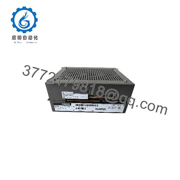
PC-E984-685R
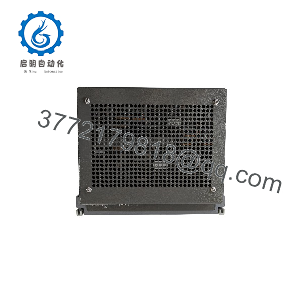
PC-E984-685R
Installation & Configuration Guide
Stage 1: Pre-Installation Preparation (≈15 minutes)
⚠️ Safety First: Notify operations of downtime and place the controlled process in a safe state — if this is an S911 Hot Standby pair, check which unit is primary before touching anything. Lock out/tag out the controller supply branch. Wait 5 minutes for discharge, then verify 0 V at the power terminals with your multimeter.
- Tools Required: ESD wrist strap, multimeter (Fluke 115 or equivalent), PH1/PH2 screwdrivers, wire labels, Modbus serial cable for the programming PC (or SA85 Modbus Plus card and RG-6 coax), smartphone for photos.
- Data Backup: Connect with Modsoft/ProWORX and upload the complete user program and reference tables before pulling anything. The 984-685 holds its user program on memory daughter boards — a good program backup is your lifeline if the old boards turn out to be marginal. Photograph both DIP switch banks (8 switches top, 7 switches bottom on the 685 — the Modbus Plus node address and Modbus Port 1 settings live there). Record the executive version label and the Modbus Plus node address. If the application is a Hot Standby pair, back up both units.
Stage 2: Removing the Old Controller (≈15 minutes)
- Photograph the front panel and slot position, all cable connections (Modbus serial, MB+ coax, I/O bus cables), and both DIP switch banks.
- Disconnect cabling. The MB+ coax uses BNC-style connectors — support the connector body while turning the ring, never yank the cable.
- Release the module from the H819 housing slot and slide it straight out.
- Note the daughter board configuration inside (executive and memory boards) — the replacement must carry the same or compatible boards.
- Inspect the housing slot backplane contacts for corrosion or bent fingers.
⚠️ Keep the old controller on the bench until the replacement runs the full program. Its memory daughter boards may be your recovery source if the uploaded backup turns out to be stale.
Stage 3: Installing the New Controller (≈15 minutes)
- Ground yourself with the ESD strap. Handle the controller by its metal frame, not the board edges.
- Verify the nameplate: PC-E984-685R, matching executive/memory daughter boards, and the supply voltage selector position (115 vs. 230 VAC) — check the selector against your mains before power-up; a wrong selection can damage the supply.
- Configuration clone (crucial): Replicate both DIP switch banks from your photos — the 685 uses an 8-switch bank on top and a 7-switch bank on the bottom (the 685E uses a single bottom 8-switch bank; don’t confuse the documentation between the two models). The Modbus Plus node address must be unique on the network — a duplicate MB+ address takes down peer-to-peer traffic for every node on that segment. This is the most common rookie mistake on this controller, and I can’t stress it enough: take a picture before you pull it.
- Slide the controller into the housing slot until fully seated; secure the retaining hardware.
- Reattach the Modbus serial, MB+ coax, and I/O bus cables per your labels.
Self-Checklist: [ ] DIP banks match photo, [ ] MB+ node address unique, [ ] Supply selector matches mains, [ ] Daughter boards compatible, [ ] Module fully seated and secured.
Stage 4: Power-On & Testing (≈15 minutes)
- Pre-power check: Meter the supply input for correct voltage and no shorts.
- Power the controller. Watch the front-panel LEDs — the 984’s RUN/COMM LEDs indicate the boot state; healthy units pass through power-up diagnostics to RUN.
- Connect with Modsoft/ProWORX over Modbus or MB+. Verify the executive version and node address read-back before downloading anything.
- Download your backed-up user program and reference data. Verify the program checksum matches your records.
- Test Modbus Plus communication — confirm peer nodes see the controller and MSTR blocks function. If this is a Hot Standby pair, verify the primary/standby roles settled correctly.
- Dry-run test: verify inputs read correctly against known field states, cycle outputs in maintenance mode where the process permits, and confirm S908 Remote I/O drops are all responding.
- Update the maintenance log: serial number, revision, executive version, program checksum, battery/status notes.
⚠️ Troubleshooting Note: Controller won’t enter RUN — suspect an executive/memory board mismatch or a corrupt download; re-verify the backup and the board versions. No MB+ traffic — check the node address DIP settings and coax termination; MB+ is a token-passing bus and one mis-addressed node disturbs every peer. Modbus port dead — check Port 1 DIP switch settings (they’re on the controller, not just in software). Random resets — measure supply quality; the 984’s integrated supply is picky about brownouts.
Total time for an engineer familiar with 984 hardware: 45–60 minutes including program download.
Frequently Asked Questions (FAQ)
Q1: Is the PC-E984-685R obsolete, and is this a genuinely new unit?
Yes — Schneider Electric discontinued the 984 family years ago; the platform is legacy with no factory support beyond archival documentation. Our stock is New Original / New Surplus: genuine OEM units from cancelled projects and distributor liquidations, never installed. Every unit is functionally tested before shipping — power-up diagnostics on a genuine H819 housing, memory verification, Modbus and Modbus Plus communication tests — with test photos/videos available on request. Refurbished units are also available at lower cost, clearly labeled as refurbished. No blurring between conditions, ever.
Q2: What does the “R” suffix mean?
The R denotes a hardware revision of the PC-E984-685. Functionally the units are the same controller — same 16K/10K memory, same ports, same option support — but board revisions can differ in detail. If your application documentation specifies a particular revision, confirm the exact suffix at ordering; otherwise the units interchange. Honestly, for most swap-ins the suffix is a non-issue, but verify against your site records rather than assuming.
Q3: What’s the difference between the 984-685 and the 984-685E?
The 685E adds an onboard Ethernet port. The standard 685 (this unit) has Modbus and Modbus Plus only — to put it on Ethernet you need an external BM85 Bridge Multiplexer. They also differ in DIP switch layout (the 685 has two banks; the 685E has one 8-switch bank at the bottom), so documentation doesn’t interchange cleanly. If your architecture needs native Ethernet, order the 685E or a BM85, not this unit.
Q4: Will I lose my program when I pull the old controller?
The program lives on the memory daughter boards inside the old controller — pull it, and the boards stay configured. The risks are marginal boards (aged PROMs and RAM on 30-year-old hardware) and losing the physical boards entirely. So upload the program via Modsoft/ProWORX before removal, and keep the old controller intact as a backup source. One more note from experience: many 984 sites run with program copies that are years out of date compared to what’s actually in the PLC — upload from the running controller, not from the archive drive, or you’ll overwrite field fixes nobody documented.
Q5: Can I hot-swap this controller under power?
No. Beyond the obvious electrical risk, the 984-685 is a token-passing Modbus Plus node — pulling it live drops its token and forces network reconfiguration, disturbing every peer on the segment. Lock out the supply, wait for discharge, verify with a meter, then swap. In an S911 Hot Standby pair you may be able to swap the standby unit without stopping the process — but follow the standby procedure; pulling the wrong unit of the pair stops the line.
Q6: Why is your price lower than what some distributors charge?
Because Schneider no longer manufactures this controller and the remaining genuine stock moves through surplus channels at negotiated prices. We buy that inventory and price it to sell — same OEM part, functionally tested and warranted by us rather than the manufacturer. We state condition plainly on every listing: New Original, New Surplus, or Refurbished. No clones, no vague “tested working” language that hides a used unit.
Q7: What warranty do you offer?
New Original / New Surplus units: 1-year replacement warranty. Refurbished: 6 months. Every unit is tested before shipping — power-up diagnostic pass, memory read/write verification, Modbus RTU handshake on both serial ports, Modbus Plus token participation on a live test segment, and a minimum 24-hour powered run with thermal monitoring — documented in a signed test report available with the shipment. Warranty failures are replaced, no restocking fees.