
 WhatsApp: +86 16626708626
 Email:
  Phone: +86 16626708626
Description
Key Technical Specifications
| Parameter | Value |
|---|---|
| Manufacturer | Moog |
| Exact requested part number | D16-001-007 |
| Closely matching documented Moog part number | D136-001-007 |
| Controller family | MSC I |
| System | M3000 |
| Processor | PowerPC, 32-bit RISC with floating-point unit* |
| Flash EEPROM | 4 MB* |
| Ethernet | 1 interface* |
| CAN | 2 interfaces* |
| PROFIBUS-DP | 1 slave interface* |
| Position transducer interfaces | 2* |
| Supply voltage | 24 V DC, 18–36 V DC* |
| Typical current consumption | 0.5 A idle; 2 A full load* |
| Mounting | NS 35/7.5 DIN rail* |
| Dimensions | 160 × 170 × 85.5 mm* |
| Operating temperature | +5 to +55 °C* |
| Storage temperature | −25 to +70 °C* |
| Relative humidity | 10–95%, non-condensing* |
| Protection rating | IP20* |
| Operating altitude | Up to 2,000 m* |
| Standards | IEC 61131-2, EN 61000-6-2, EN 61000-6-4* |
*Specifications above come from Moog documentation for D136-001-007. They should not be treated as confirmed specifications for the requested D16-001-007 until the physical nameplate or OEM documentation confirms the part number.
Product Introduction
The requested Moog D16-001-007 should be verified against the physical nameplate before procurement. Moog’s published M3000 documentation identifies D136-001-007 as an MSC I Motion Controller with Ethernet, two CAN interfaces, PROFIBUS-DP slave communication, and two position-transducer interfaces.
For the documented D136-001-007, the controller uses a 32-bit PowerPC processor, 4 MB Flash EEPROM, 24 V DC supply, and DIN-rail mounting. The published operating range is +5 to +55 °C with IP20 protection.
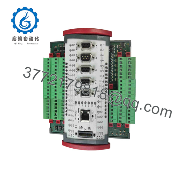
D16-001-007
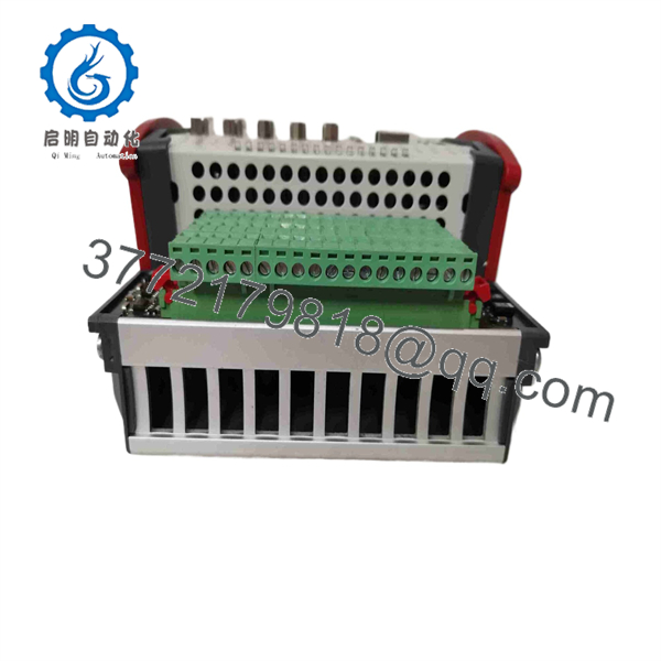
D16-001-007
Installation & Configuration Guide
Stage 1: Pre-Installation Preparation — 5–10 minutes
⚠️ Safety First: Notify operations, place the machine in a safe state, apply lockout/tagout, and isolate the controller’s 24 V DC supply. Allow at least 5 minutes for connected capacitors to discharge.
Tools Required
- ESD wrist strap and ESD-safe work surface
- PH1 screwdriver
- Digital multimeter
- Wire labels
- Smartphone or camera
- Torque-appropriate screwdriver where specified by the installation documentation
Data Backup
- Record the complete part number and hardware revision from the existing controller.
- Photograph the complete controller before removal.
- Photograph terminal wiring, connectors, DIP switches, jumpers, and network connections.
- Record Ethernet settings and PROFIBUS configuration.
- Save the current M3000 application/configuration where applicable.
- Record the existing firmware revision.
⚠️ Critical: If the existing label reads D136-001-007, do not order or install a unit marked only D16-001-007 without confirming the relationship between the two numbers.
Stage 2: Removing the Old Module — 5 minutes
- Remove the front cover or protective enclosure as applicable.
- Label every field connection before disconnecting it.
- Disconnect the wiring without pulling on conductors.
- Release the DIN-rail retaining mechanism.
- Pull the controller straight away from the mounting rail.
- Inspect the wiring terminals and surrounding area for contamination or mechanical damage.
- Inspect the 24 V supply wiring and protective earth arrangement.
Keep the removed controller beside the replacement until commissioning is complete. It provides the most reliable reference for wiring and configuration.
Stage 3: Installing the New Module — 5–10 minutes
- Put on the ESD wrist strap before handling the electronics.
- Verify the complete ordering number and hardware revision against the old controller.
- Compare connector locations and terminal assignments.
- Reproduce documented configuration settings from your photographs.
- Mount the controller on the DIN rail.
- Confirm that the retaining mechanism is fully engaged.
- Reconnect wiring according to the applicable Moog documentation.
- Verify the 24 V DC supply polarity before applying power.
Self-Checklist
- Exact part number verified
- Hardware revision checked
- Configuration documented
- Wiring labels verified
- DIN-rail latch secured
- 24 V polarity checked
- Ethernet connection checked
- PROFIBUS connection checked, if used
- CAN connections checked, if used
Stage 4: Power-On & Testing — 10–15 minutes
- Measure the incoming DC supply with a multimeter before energizing the controller.
- Energize the controller while keeping field equipment in a controlled state.
- Observe startup LEDs and controller status indications.
- Connect the applicable Moog engineering/configuration environment.
- Confirm controller identification and firmware information.
- Verify Ethernet communication.
- Verify PROFIBUS-DP communication if the installation uses the interface.
- Verify CAN communication where applicable.
- Confirm position-transducer feedback.
- Run the application without commanding hazardous machine movement.
- Perform a controlled dry run.
- Return the equipment to production only after I/O, feedback, communication, and motion checks pass.
⚠️ Troubleshooting: A communication failure immediately after replacement does not automatically indicate a defective controller. Check the part-number revision, firmware, network parameters, bus addressing, termination, connector seating, and application configuration first.
Moog’s documentation specifies 24 V DC, 18–36 V DC for the documented D136-001-007 controller, with approximately 0.5 A idle consumption and 2 A at full load.
Frequently Asked Questions (FAQ)
1. Is Moog D16-001-007 the same as ?
I would not assume that they are identical. The Moog documentation I found explicitly lists as an MSC I Motion Controller. I did not find equivalent OEM documentation confirming D16-001-007. Verify the physical nameplate before purchasing or installing a replacement.
2. What is the documented used for?
Moog identifies as an MSC I Motion Controller in the M3000 product family. Its documented interfaces include Ethernet, two CAN interfaces, one PROFIBUS-DP slave interface, and two position-transducer interfaces.
3. Can this controller be hot-swapped?
Do not assume hot-swap capability. The published documentation identifies the controller as a 24 V DC-powered DIN-rail device but does not establish hot-swapping as an approved replacement procedure. For a live plant replacement, follow the machine/OEM shutdown procedure rather than removing the controller under power.
4. Will I lose the motion-control program when replacing the controller?
The replacement should not be treated as a simple plug-and-play swap. Before removing the existing controller, back up the application/configuration and record firmware and communication parameters. Whether the application can be restored directly depends on the M3000 configuration and engineering environment used by the machine.
5. Does the controller use PROFIBUS-DP?
For , yes. Moog specifies one PROFIBUS-DP slave interface. The closely related D136-001-008 does not have that PROFIBUS-DP interface, which is an important ordering distinction.
6. Is obsolete?
A current third-party industrial-parts listing identifies as discontinued by the manufacturer. Moog’s own documentation also identifies it within its legacy M3000 controller documentation. Availability should therefore be checked against the actual stock condition rather than assumed from a catalog listing.
7. What should I provide when requesting a replacement?
Provide the complete nameplate part number, hardware revision, serial number, firmware revision, and clear photographs of the controller and connectors. For this particular request, that is especially important because the documented Moog part number is , while the requested number is . Verification before shipment can prevent installing the wrong controller.



