
 WhatsApp: +86 16626708626
 Email:
  Phone: +86 16626708626
Description
Key Technical Specifications
- Manufacturer: Moog
- Model: G122-824-002
- Series: G122-824
- Product Type: P-I servo amplifier
- Control Modes: Proportional, integral, or combined P + I
- Supply Voltage: 24 V DC nominal
- Operating Supply Range: 22–28 V DC
- Input 1: Single-ended, scalable configuration
- Input 2: Selectable 4–20 mA or ±10 V
- Feedback Input: Differential; selectable 4–20 mA or ±10 V
- Output: Selectable voltage or current
- Voltage Output: ±10 V
- Current Output: Selectable current ranges, up to ±100 mA combined selection
- Dither: 200 Hz, selectable on/off
- Enable Input: External 24 V DC
- Feedback Excitation: Regulated output for feedback transducer
- Mounting: DIN rail
- Dimensions: Approximately 100 × 108 × 45 mm
- Weight: Approximately 0.18 kg
- Operating Temperature: 0 to +40 °C
- Compliance: CE marked
The G122-824-002 uses internal selector switches for control mode, signal range, feedback type, and output configuration. Published product data identifies the module as a compact DIN-rail analog servo amplifier for closed-loop hydraulic control.
The -002 revision is reported as the functional replacement for G122-824-001, with 4–20 mA capability added at Input 2, an output-step push button, and improved thermal performance. Verify these revision-specific features against the unit’s documentation before installation.
Product Introduction
The Moog G122-824-002 is a configurable analog P-I servo amplifier for closed-loop electrohydraulic control. It accepts command and feedback signals, applies proportional and integral control, and drives a servo valve or actuator through a selectable voltage or current output.
The module fits DIN-rail control panels and includes front-panel potentiometers, LEDs, test points, an enable input, feedback excitation, and selectable 200 Hz dither. It is commonly used in hydraulic actuator, governor, turbine, and servo-valve control loops where signal scaling and loop tuning must match the installed equipment.
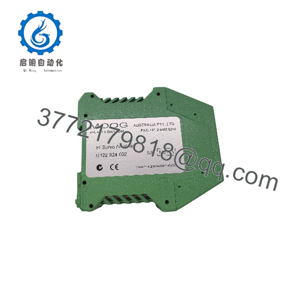
G122-824-002
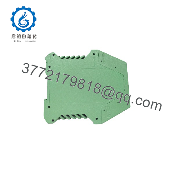
G122-824-002
Troubleshooting Quick Reference
| Symptom | Possible Cause | Relevance to This Part | Quick Check Method | Recommendation |
|---|---|---|---|---|
| No LEDs or no response | Missing 24 V DC supply, blown fuse, or incorrect polarity | ✅ High | Measure 22–28 V DC at the amplifier supply terminals with a calibrated multimeter | Check the power supply, fuse, polarity, and common before replacing the amplifier |
| Output remains at zero | Enable input inactive or control signal missing | ✅ High | Confirm external enable voltage and measure the command input directly at the terminals | Restore the enable circuit or input signal before condemning the module |
| Valve drives fully open or closed | Feedback polarity, scaling, or input selection is incorrect | ✅ High | Measure command and feedback signals; verify ±10 V versus 4–20 mA selector settings | Remove the hydraulic demand and verify configuration before further testing |
| Output signal is the wrong range | Internal output selector or wiring does not match the valve | ✅ High | Measure the output with the valve disconnected only under an approved test procedure; check the output configuration | Match the output mode and current range to the servo-valve specification |
| Hydraulic actuator oscillates | Excessive proportional gain, integral setting, feedback noise, or wrong polarity | ✅ High | Monitor command, feedback, and output with an oscilloscope or suitable data-acquisition equipment | Recheck loop tuning and feedback wiring before replacing the amplifier |
| Actuator responds slowly or leaves steady-state error | Insufficient gain, incorrect integral setting, or restricted hydraulic supply | ✅ Medium | Compare command and feedback signals during a controlled step test | Tune P/I settings only under an approved commissioning procedure |
| Valve sticks near zero command | Dither disabled, incorrect dither setting, or hydraulic valve problem | ✅ Medium | Verify the 200 Hz dither configuration and inspect the valve’s mechanical and hydraulic condition | Enable dither only if appropriate for the valve and application |
| Feedback signal is unstable | LVDT/transducer fault, excitation problem, shielding issue, or loose wiring | ❌ Low to ✅ Medium | Measure feedback excitation and signal stability at the amplifier terminals | Check the transducer, cable shield, grounding, and mechanical linkage first |
| Replacement fails despite correct part number | Internal switches differ from the original unit | ✅ High | Photograph and compare selector settings, jumpers, and terminal wiring with the removed amplifier | Reconfigure the replacement to the approved application settings |
| Amplifier overheats | Cabinet temperature, blocked ventilation, excessive output load, or wiring fault | ✅ Medium | Measure cabinet temperature and inspect output load and ventilation | Correct the environmental or load issue before replacing the module |
Critical warning: This is an analog servo-loop component, not a plug-and-play PLC analog output card. Disable hydraulic motion or place the equipment in a safe test state before measuring or changing output wiring. Contact technical support with photos of the nameplate, internal selector settings, wiring, loop drawings, and diagnostic measurements if the fault remains unresolved.
Frequently Asked Questions
What is the Moog G122-824-002 used for?
It is a P-I servo amplifier for closed-loop electrohydraulic control. The module processes command and feedback signals, applies proportional and integral control, and drives a servo valve or actuator.
Is the G122-824-002 a PLC or DCS I/O module?
No. It is a dedicated analog servo amplifier. A PLC, DCS, turbine controller, or governor may provide the command signal, but the G122-824-002 performs the local servo-loop processing and valve-drive function.
Is it a direct replacement for G122-824-001?
The is reported as the functional replacement for G122-824-001. However, verify the application configuration because input ranges, feedback type, output mode, internal switches, and P/I settings must match the original installation.
What signals does it accept?
The amplifier uses two single-ended inputs and one differential feedback input. Depending on the selected configuration, Input 2 and the feedback input can use 4–20 mA or ±10 V signals. Confirm the actual terminal assignment and internal selector settings before wiring.
Can it drive any servo valve?
No. The output must match the valve’s required voltage or current range, polarity, load, and enable behavior. Check the servo-valve datasheet and the existing loop drawings; do not assume that a matching Moog brand is sufficient.
What should I verify before replacing the unit?
Record the original amplifier’s wiring, selector-switch positions, P/I adjustments, command signal, feedback signal, output mode, enable logic, and supply voltage. Take photographs before removal. This is especially important when replacing a G122-824-001 with the -002 revision.
Why is the replacement cheaper than a factory-supplied unit?
Independent industrial inventory may include New Surplus, discontinued stock, or Refurbished and tested units. The price alone does not establish condition or authenticity. Request clear photographs, serial and revision information, test documentation, warranty terms, and return conditions before purchase.



