
 WhatsApp: +86 16626708626
 Email:
  Phone: +86 16626708626
Description
Key Technical Specifications
- Manufacturer: Moog
- Model: G403-552A
- Product Type: Electrohydraulic servo valve
- Valve Architecture: Three-stage servo valve, according to current product listings
- Command Signal: Typically ±10 V analog
- Feedback: Verify application-specific feedback and monitoring configuration
- Rated Flow: Verify from the valve nameplate and original Moog datasheet
- Operating Pressure: Verify from the nameplate and hydraulic circuit documentation
- Frequency Response: Application-dependent; do not substitute a generic G403 value
- Hydraulic Fluid: Use only the fluid specified for the installed valve and seals
- Cleanliness: Maintain the hydraulic cleanliness level specified by Moog for the exact valve configuration
- Ports: Verify mounting face, port pattern, and port size before installation
- Electrical Connector: Confirm connector type and pinout against the original valve
- Null Bias: Record the original null position and command current before removal
- Operating Temperature: Verify the exact rating from the valve datasheet
- Serial Number: Required for precise configuration and service verification
Public listings consistently identify the G403-552A as a Moog servo-valve product, but published descriptions conflict on whether it is a two-stage or three-stage design and provide inconsistent flow, pressure, temperature, and frequency-response figures. Treat the nameplate, serial number, and original Moog configuration sheet as controlling data.
Product Introduction
The Moog G403-552A is an electrohydraulic servo valve for closed-loop control of hydraulic actuators. It converts a low-level analog command into controlled hydraulic flow for applications such as turbine governing, test equipment, industrial motion, and force or position control.
This is a configuration-sensitive hydraulic component. Valve stage, rated flow, pressure, coil characteristics, mounting pattern, electrical connector, and null adjustment must match the existing system. Confirm the exact Moog datasheet using the valve serial number before approving a replacement.
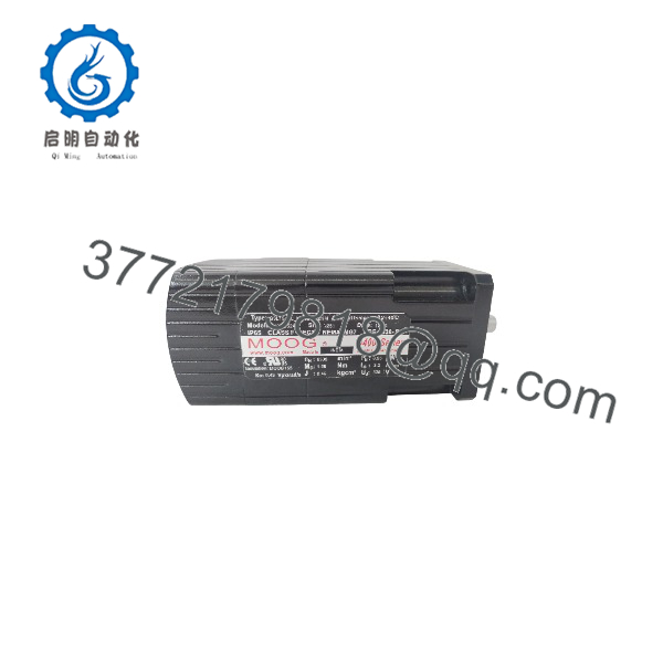
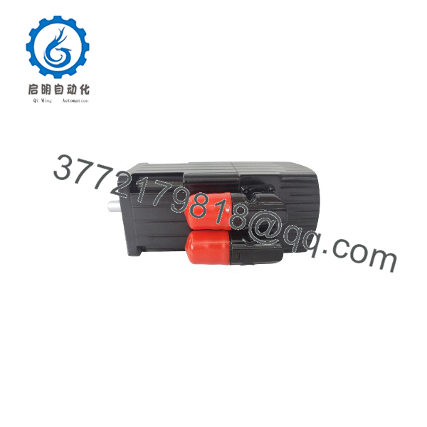
G403-552A
Troubleshooting Quick Reference
| Symptom | Possible Cause | Relevance to This Part | Quick Check Method | Recommendation |
|---|---|---|---|---|
| Actuator does not move | No command signal, no hydraulic pressure, blocked supply, or valve coil fault | ✅ High | Measure the command signal at the valve connector and verify hydraulic supply pressure at the manifold | Check the controller, pump, filters, and wiring before replacing the valve |
| Actuator moves in the wrong direction | Command polarity, spool orientation, or hydraulic port wiring is incorrect | ✅ High | Compare command polarity and valve port markings with the approved hydraulic schematic | Stop testing, isolate pressure, and correct the installation before applying further motion |
| Actuator moves fully to one end | Loss of feedback, incorrect command scaling, failed amplifier, or valve null shift | ✅ High | Monitor command and feedback signals; measure coil current and compare with the control-system documentation | Check the servo amplifier and feedback loop before condemning the valve |
| Excessive oscillation | Hydraulic contamination, incorrect loop gain, feedback noise, or valve wear | ✅ High | Trend command, feedback, and valve-drive current; inspect filter differential pressure and fluid cleanliness | Correct tuning and contamination issues first; then perform valve leakage and response testing |
| Slow actuator response | Restricted filter, low supply pressure, worn spool, or incorrect valve rating | ✅ Medium | Measure pressure upstream and downstream of filters and compare actual flow with the valve specification | Do not substitute a valve with a different flow rating |
| Large null offset | Mechanical wear, contamination, amplifier adjustment, or installation misalignment | ✅ High | With hydraulic pressure controlled, measure output movement at zero command and compare with recorded null data | Adjust only under the approved commissioning procedure; return the valve for service if null cannot be restored |
| External hydraulic leakage | Damaged seals, loose fittings, incorrect O-rings, or manifold damage | ✅ High | Depressurize the system and inspect the valve body, mounting face, and fittings | Replace seals only when approved for the exact valve; do not tighten pressurized fittings |
| Command signal present but no coil current | Open circuit, failed driver, connector fault, or internal coil problem | ✅ High | Isolate power and measure wiring continuity; compare coil resistance with the Moog documentation | Check the driver and connector before replacing the valve |
| Valve fails after installation | Incorrect connector pinout, incompatible revision, contaminated oil, or wrong mounting configuration | ✅ High | Compare the removed and replacement valve labels, connector wiring, port pattern, and configuration records | Do not wire by memory; verify every connection against the original documentation |
| Hydraulic system becomes contaminated | Internal valve wear or debris introduced during installation | ✅ Medium | Inspect filter elements and obtain a hydraulic-fluid cleanliness sample | Flush and filter the system before installing another precision valve |
Critical warning: Do not install this valve based on the model number alone. Verify the complete part number, nameplate data, serial number, coil configuration, porting, rated flow, pressure, and command interface. Contact technical support with valve photos, the hydraulic schematic, command and feedback measurements, and diagnostic logs if the fault remains unresolved.
Frequently Asked Questions
What is the Moog G403-552A used for?
It is used in closed-loop electrohydraulic systems where a controller must regulate actuator position, force, velocity, or turbine-control movement. Typical applications include test systems, industrial hydraulic actuators, and power-generation equipment.
Is the G403-552A a servo motor?
No. The -552A should be treated as a Moog electrohydraulic servo-valve assembly. Several reseller pages incorrectly label this part number as a servo motor or servo drive, so verify the physical item and nameplate before purchase.
Is it a direct replacement for another Moog valve?
A direct replacement cannot be confirmed fr” alone. Match the complete model, revision, serial number, mounting pattern, port arrangement, connector, command signal, coil characteristics, rated flow, and pressure. A valve that physically mounts may still be hydraulically or electrically wrong.
What command signal does it require?
Public product listings commonly describe a ±10 V analog command, but the exact interface must be verified against the valve’s original documentation and the installed servo amplifier. Check whether the system uses differential or single-ended signaling, command scaling, enable logic, and any feedback circuit.
Can I install it without recalibrating the system?
Do not assume that installation is calibration-free. Record the original null position, amplifier settings, feedback scaling, and actuator behavior before removal. After installation, perform a controlled null, polarity, leakage, response, and full-stroke verification with hydraulic motion secured.
What hydraulic cleanliness is required?
Precision servo valves are highly sensitive to contamination. Use the cleanliness level specified by Moog for the exact configuration, flush the lines, replace or inspect filters, and keep open ports capped during installation. Do not rely on a generic filter rating when the original system specification is available.
What condition is the available unit?
The seller should identify the exact condition as New Original, New Surplus, or Refurbished and tested. Request photos of the nameplate, serial number, connector, mounting face, ports, packaging, and test report. For a used or refurbished valve, also request leakage, null, and functional test results rather than accepting a visual inspection alone.



