
 WhatsApp: +86 16626708626
 Email:
  Phone: +86 16626708626
Description
Key Technical Specifications
| Parameter | Value |
|---|---|
| Manufacturer | MOOG |
| Full Model Number | T161-903A-00-H1-2-AA |
| Product Series | T161 |
| Product Architecture | WinDrive |
| Product Type | Servo amplifier / servo controller / drive control module |
| Primary Function | Closed-loop motor torque, speed, and position control |
| Control-Interface Family | Analog ±10 V interface family; confirm the exact suffix-dependent command and feedback configuration |
| T161 Model Range | T161-901 through T161-903 models are covered by the available analog-interface manual reference |
| Motor Compatibility | Must match the installed motor voltage, current, feedback device, winding data, and machine load profile |
| Feedback Compatibility | Verify encoder, resolver, tachometer, or other feedback configuration from the full drive nameplate and existing wiring |
| Command Compatibility | Verify analog command scaling, enable logic, fault-reset method, reference polarity, and controller output configuration |
| Drive Configuration | Record all DIP switches, jumpers, parameter values, firmware labels, and terminal assignments before removal |
| Mechanical Installation | Verify mounting dimensions, ventilation clearance, grounding arrangement, heat dissipation, and connector layout against the installed unit |
| Lifecycle Status | Legacy / high obsolescence exposure |
| Stocking Recommendation | Min: 1 exact verified unit on-site for a critical unique axis; Max: 2 only when multiple machines use the same full code and a failure would cause material production loss |
| Procurement Requirement | Do not source by “T161-903” alone; match every suffix in -903A-00-H1-2-AA and verify the motor-drive-controller combination |
A published operating-instructions reference covers -901 through -903 servo controllers with an analog ±10 V interface. Market sources identify this exact part number as a MOOG servo amplifier or controller, while a source for the broader family describes a related -903A model as a servo-control module with CAN profile mode and 30 A peak current. The latter value must not be assigned to this exact H1 configuration without nameplate confirmation.
Product Introduction & Supply Chain Strategy
The MOOG T161-903A-00-H1-2-AA is a -series servo amplifier for closed-loop industrial motion control. It accepts machine control commands and regulates the connected servo motor to achieve controlled torque, speed, and position behavior. It is typically installed in equipment where consistent axis response matters, such as converting, test equipment, hydraulic-electric motion systems, specialty machinery, and automated production machines.
This product is a Brand New Surplus unit. It is not used, not pulled from a decommissioned plant, and not refurbished. All modules undergo rigorous quality verification to ensure OEM-level reliability. For an aging motion platform, one exact configured buffer stock drive is usually more cost-effective than an emergency retrofit. A proper last-time-buy decision should weigh installed-base commonality, lead time variability, stored parameter availability, and the Total Cost of Ownership (TCO) of an unplanned axis outage.
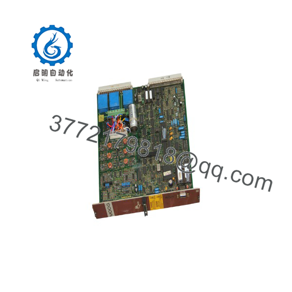
T161-903A-00-H1-2-AA
Installation & Configuration Guide
Stage 1: Pre-Installation
- Stop the machine using the approved shutdown procedure. Record active MOOG drive faults, controller alarms, motion-axis status, actual position, command position, following error, motor current, speed, and any process conditions related to the failure.
- Apply lock-out/tag-out to incoming AC supply, DC bus circuits, 24 V control power, motor circuits, external command circuits, pneumatic or hydraulic energy, stored mechanical energy, and all external motion sources.
- Verify absence of voltage with appropriately rated instruments. Wait for the drive’s DC bus and internal energy-storage circuits to discharge according to the machine and MOOG documentation.
- Secure vertical, suspended, tensioned, or gravity-loaded axes mechanically. Do not depend on the servo system to hold a load during maintenance.
- Wear a grounded ESD wrist strap and use an ESD-safe work surface when handling drive connectors, control wiring, feedback interfaces, or configuration devices.
- Photograph the installed drive from all sides. Capture the full nameplate, suffix code, connector labels, terminal assignments, wire colors, shield terminations, jumpers, DIP switches, firmware or memory labels, mounting arrangement, airflow path, and grounding points.
- Back up all machine and drive data before removal. Preserve controller logic, analog-command scaling, motor data, current limits, speed limits, torque limits, acceleration and deceleration values, tuning data, fault settings, I/O logic, enable sequence, reference polarity, and homing information.
- Inspect the motor, coupling, gearbox, load, feedback cable, motor cable, cabinet cooling, line power, grounding, and external control signals. Eliminate root causes such as motor winding faults, encoder faults, shorted output cables, poor grounding, loose power connections, mechanical binding, or an overloaded axis before installing the replacement drive.
Stage 2: Removal
- Confirm that the DC bus is fully discharged and that all relevant control and motor circuits remain isolated.
- Label every connector, terminal wire, shield, ground strap, and external interface before disconnection. Do not trust legacy panel labels without comparison to your photographs and drawings.
- Disconnect motor power, protective earth, feedback wiring, analog command wiring, enable/fault-reset circuits, communications wiring, and auxiliary I/O by connector housing or terminal hardware. Do not pull on conductors.
- Protect analog and feedback wiring from static discharge, oil, moisture, metal debris, and mechanical damage.
- Remove retaining screws, clips, brackets, or rack hardware in the documented sequence. Support the drive during removal.
- Avoid flexing connectors, striking the enclosure, or applying force to terminals. Internal power and control components can be damaged by rough handling.
- Inspect cable terminals, connector pins, grounding hardware, cabinet fans, filters, heat sinks, and mounting surfaces before fitting the New Surplus unit.
- Preserve the removed drive in an ESD-safe bag with the asset number, full fault description, parameter-backup location, and removal date for controlled evaluation.
Stage 3: Installation
- Compare the replacement and removed nameplates side by side. Confirm the exact full model number, -903 frame, suffix string, power rating, control-interface configuration, feedback type, connector layout, and revision identification.
- Do not proceed if any suffix differs unless a written MOOG-approved or engineering-approved cross-reference confirms compatibility.
- Mount the drive in the original orientation and location. Maintain required ventilation clearances and restore all factory shielding, heat sinking, and grounding provisions.
- Reinstall protective earth first. Confirm low-impedance grounding between the drive chassis, cabinet ground bar, motor frame, and machine protective-earth system.
- Reconnect motor power, feedback, analog command, control power, enable, fault-reset, and auxiliary I/O exactly as documented.
- Keep low-level analog-command and feedback cables physically separated from motor output cables and high-current conductors. Restore shield termination exactly as found unless approved drawings specify a correction.
- Replicate every documented DIP switch, jumper, hardware link, and removable configuration-device setting. Incorrect settings can alter current limit, feedback type, command polarity, or fault behavior.
- Load only the validated parameter set that belongs to the exact motor, feedback device, controller, and mechanical axis.
- Verify terminal torque and connector latching. Inspect for loose screws, pinched wiring, unseated plugs, displaced insulating barriers, or tools left in the cabinet.
Stage 4: Power-On & Testing
- Before applying full power, test low-voltage control rails and relevant motor circuits for shorts to ground or phase-to-phase faults.
- Apply control power first where the machine architecture permits. Check the drive status indicators and controller diagnostics for initialization, feedback, enable, current-loop, and fault errors.
- Verify that the analog command is at zero before enabling the axis. An incorrect ±10 V polarity or offset can command unintended motion.
- Confirm safety circuits, emergency stop, overtravel switches, interlocks, brake controls, and mechanical restraints before enabling servo power.
- Enable the drive with the process area clear. Start with a low-speed, low-load jog and confirm motor direction, actual speed, position feedback, motor current, command-response polarity, and absence of vibration or abnormal noise.
- Verify command scaling. For example, if the controller sends +10 V+10 V for maximum forward speed, confirm that the motor rotates in the required direction and reaches the configured limit without overspeed or following error.
- Perform the approved homing and low-load functional test. Gradually increase speed, torque demand, and load while monitoring current, fault history, temperature, tracking error, and process response.
- Return the machine to automatic production only after completing the documented acceptance test. Record the installed drive serial number, firmware or memory revision, parameter-file version, commissioning results, and remaining buffer stock.
Firmware/Software Versions & Upgrade Notes
- Recommended firmware version: Retain the installed drive firmware, removable memory, and validated parameter revision during a direct replacement. The exact suffix -903A-00-H1-2-AA must govern the configuration; publicly available market information does not provide a verified MOOG firmware matrix for this exact suffix.
- Analog-interface control: The available manual reference identifies -901 through -903 models as servo controllers with an analog ±10 V interface. Confirm command polarity, command scaling, analog ground reference, enable logic, and fault-reset behavior before enabling motion.
- Suffix control: Do not substitute a different -903A suffix without engineering review. A rela-10-E5-2-9A is described as a CAN-profile drive module with 30 A peak current, demonstrating t variants can differ materially in interface and capability.
- Parameter retention: Drive parameters can reside in drive memory, external engineering software, the machine controller, or removable configuration devices. Back up all locations before removing the failed unit.
- Backward compatibility: An earlier firmware or configuration revision may not support later feedback devices, controller signals, communications options, or parameter files.
- Forward compatibility: A later or alternate MOOG drive may require different motor data, feedback cables, command interfaces, tuning values, safety logic, and machine controller changes. Treat it as a retrofit, not a spare replacement.
- Upgrade warning: Do not upgrade drive firmware during an emergency replacement unless the prior version is unavailable and the new version has passed compatibility testing. Firmware changes can affect command scaling, I/O timing, fault thresholds, tuning behavior, and axis response.
- Downgrade warning: Do not downgrade firmware or transfer a configuration device without a verified backup, recovery method, and compatibility confirmation. A failed downgrade can make the motion axis unavailable.
- Spare-control recommendation: Store the spare with a full nameplate photograph, motor and feedback details, parameter backup, wiring drawings, axis-tuning record, firmware or memory label record, and approved commissioning checklist.
Frequently Asked Questions (FAQ)
Are these really new units?
Yes. This supply policy applies only to New Original / New Surplus inventory. A New Surplus MOOG drive should have no field-installation wear, damaged terminals, bent connector pins, heat discoloration, altered components, non-original solder work, contamination, or missing labels. Incoming QC should verify the complete part number, serial number, suffix string, enclosure condition, connector condition, board or component markings where accessible, ESD-safe packaging, and functional-test evidence when a compatible test arrangement is available.
Why is New Surplus pricing lower than OEM new but higher than lower-cost alternatives?
OEM pricing reflects current manufacturer supply channels and support structures. New Surplus pricing reflects the cost of locating, authenticating, preserving, testing, and warranting genuine legacy inventory. Lower-cost alternatives can hide stressed power devices, degraded capacitors, damaged feedback inputs, unstable analog-command circuits, incorrect revisions, or undocumented electrical modifications. A low purchase price is not a favorable outcome if the replacement causes a second outage or triggers a wider axis retrofit.
Is -00-H1-2-AA obsolete or EOL?
Treat -00-H1-2-AA as a legacy motion-control spare with high obsolescence exposure. Current market listings show continued secondary-market availability, but they do not confirm active factory production, lifecycle support, or an approved direct replacement.
For a critical machine, hold one exact, verified buffer stock unit on-site. Consider a second only if several critical axes use the identical full suffix, cross-site sharing cannot meet the recovery-time target, and the cost of extended downtime exceeds the additional holding cost.
Can I hot-swap the MOOG servo amplifier?
No. Do not install or remove the drive while energized. It connects to hazardous power circuits, motor outputs, feedback signals, analog command wiring, and safety-related control circuits. Isolate all energy sources, verify DC-bus discharge, secure the mechanical axis, and follow the machine builder’s approved procedure before replacement.
Will replacing the drive erase machine programming?
The machine controller generally retains its program, but the servo drive can hold motor data, current limits, tuning parameters, analog scaling, fault behavior, I/O configuration, and feedback settings. Back up the controller project and drive configuration before removal. After installation, verify the restored parameter set before enabling any automatic motion.
Can I substitute another -903 or a different servo amplifier?
Not without an engineering-approved cross-reference. The exact suffix controls key characteristics such as power configuration, motor-feedback interface, analog or network control method, connector layout, firmware, and internal options. A rela variant is described with CAN profile mode, which may not match this analog-interface application.
A different drive may require changes to the motor cable, feedback cable, controller output, safety circuits, panel layout, tuning parameters, and commissioning procedure.
What warranty and QC documentation should accompany the spare?
Specify a written 12 month warranty, subject to correct storage, installation, and operating conditions. Request complete nameplate and serial-number photographs, connector and terminal inspection records, enclosure and cooling-surface inspection, ESD-safe packaging evidence, power-on or functional-test evidence where a compatible setup is available, and final QC sign-off. File those records with the motion-axis asset history so the spare can be installed rapidly and with controlled technical risk.



