
 WhatsApp: +86 16626708626
 Email:
  Phone: +86 16626708626
Description
3. Key Technical Specifications
| Parameter | Value |
|---|---|
| Manufacturer | Motorola Computer Group |
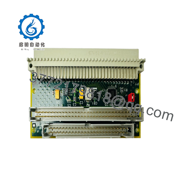
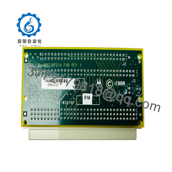
| Model Number | 01-W3216F-01A |
| Product Family | MVME761 Transition Module |
| Application | Rear I/O Interface for VME Single Board Computers |
| Compatible SBCs | MVME260x, MVME270x, MVME360x, MVME460x Series |
| Ethernet Interface | 10Base-T / 100Base-TX |
| Serial Ports | 2 × EIA-574 Asynchronous Ports |
| Additional Serial Support | EIA-232-D, EIA-530, V.35, X.21 Configurable |
| Parallel Interface | IEEE 1284-I Compatible |
| SIM Connectors | 2 × 60-pin Serial Interface Module Connectors |
| Backplane Connection | 3-Row P2 VMEbus Interface |
| Operating Environment | Industrial Control and Embedded Computing Systems |
The available documentation strongly indicates that 01-W3216F-01A belongs to the MVME761 transition module family and serves as the rear I/O breakout interface for Motorola VMEbus single-board computer platforms. Closely related variants (01-W3216F01, 01-W3216F-01B, 01-W3216F-02A) share the same architecture and functionality.
4. Product Introduction
The Motorola 01-W3216F-01A is a VMEbus transition module used with Motorola MVME2600, MVME2700, MVME3600, and MVME4600 series single-board computers. It routes communication signals from the SBC rear P2 connector to standard field interfaces including Ethernet, serial communications, and parallel I/O.
In field deployments of legacy VME control systems, these modules are often retained during processor upgrades because they simplify cable management and preserve existing field wiring. The module supports multiple industrial communication standards and provides a practical interface layer between the VME rack and external equipment.

- 01-W3216F-01A
- 01-W3216F-01A
5. Installation & Configuration Guide
Stage 1: Pre-Installation Preparation (10 Minutes)
⚠️ Safety First
- Notify operations personnel of planned downtime.
- Place the controlled system into a safe state.
- Apply lockout/tagout procedures.
- Remove rack power.
- Wait at least 5 minutes for power supply capacitors to discharge.
Tools Required
- ESD wrist strap
- PH1 screwdriver
- Fluke 115 or equivalent multimeter
- Wire labels
- Smartphone for documentation
- Flashlight
Data Backup
- Export controller configuration.
- Record Ethernet settings and node addresses.
- Photograph all cable connections.
- Photograph any jumpers or configuration switches.
- Save system diagnostics before shutdown.
Stage 2: Removing the Old Module (5 Minutes)
- Remove any rack covers or rear access panels.
- Label all attached cables before disconnecting.
- Disconnect Ethernet, serial, and peripheral cables.
- Release retaining hardware.
- Pull the module straight out.
⚠️ Do not rock the board excessively. Bent P2 connector pins are common causes of replacement failures.
- Inspect the VME backplane for:
- Bent contacts
- Dust accumulation
- Corrosion
- Foreign objects
⚠️ Keep the original module available until the replacement passes operational testing.
Stage 3: Installing the New Module (10 Minutes)
- Attach ESD protection before handling the board.
- Verify the exact part number matches the intended replacement.
Configuration Clone (Critical)
- Compare jumpers and switch settings with the removed module.
- Match node addressing exactly.
- Verify termination settings where serial interfaces are used.
❗ This is the most common rookie mistake. Take photos before removal and duplicate every setting exactly.
- Insert the module squarely into the P2 connector.
- Ensure full seating into the backplane.
- Secure mounting hardware.
- Reconnect all field wiring.
Self-Checklist
- Part number verified
- Jumpers matched
- Wiring secured
- Connector fully seated
- ESD precautions followed
Stage 4: Power-On & Testing (10 Minutes)
Pre-Power Check
- Verify no shorts exist on the supply rails.
- Inspect connectors one final time.
Power-On Procedure
- Energize the VME rack only.
- Observe startup indicators.
- Verify SBC boot sequence.
- Connect diagnostic software.
- Confirm Ethernet communication.
- Verify serial port operation.
- Perform loopback tests where applicable.
- Test all required I/O paths.
Troubleshooting
⚠️ Solid fault indicators often indicate firmware or compatibility issues between the SBC and transition module family.
⚠️ No communications typically point to:
- Incorrect cabling
- Incorrect jumper settings
- Connector seating issues
- Backplane pin damage
6. Frequently Asked Questions (FAQ)
Q1. Can I hot-swap the 01-W3216F-01A?
No.
Most MVME2600/3600/4600 systems were not designed for hot-swapping transition modules. Removing the board under power can interrupt bus signals and potentially damage the backplane. Shut the rack down first.
Q2. Is the 01-W3216F-01A obsolete?
Yes.
This module belongs to a legacy Motorola VME architecture that has been out of mainstream production for many years. Most available inventory today consists of tested surplus or refurbished stock. Availability can vary significantly.
Q3. What systems is this module compatible with?
Available documentation links the MVME761 family to:
- MVME260x
- MVME270x
- MVME360x
- MVME460x
Always verify exact SBC compatibility against the installed system documentation before ordering.
Q4. Will I lose my application software if I replace this module?
Normally no.
The 01-W3216F-01A functions as a transition interface board. Application software typically resides on the SBC itself rather than on the transition module. Still, create a backup before maintenance.
Q5. What is the most common installation mistake?
❗ Incorrect jumper replication.
I’ve seen technicians spend hours troubleshooting Ethernet and serial communication faults only to discover one jumper was left in the factory default position. Photograph everything before removal.
Q6. Why are surplus units often much cheaper than OEM pricing?
Because the OEM production line is long discontinued.
Most available units come from decommissioned systems, excess inventory, or certified surplus stock. A tested surplus module can cost a fraction of the original procurement price while still meeting operational requirements.


