
 WhatsApp: +86 16626708626
 Email:
  Phone: +86 16626708626
Description
3. Key Technical Specifications
| Parameter | Value |
|---|---|
| Model | EMI-1 |
| Part Number | 01-W3737B-01B |
| Manufacturer | Motorola / Emerson |
| Bus Architecture | VMEbus |
| Product Type | Environmental Monitoring Module |
| Status Indicators | TMP/OFF LED, Sensor LED |
| Front Panel Controls | Chassis Switch, SEN PWR Switch |
| Installation Type | VMEbus Card Slot |
| Application | Chassis Monitoring and Sensor Management |
| Form Factor | VMEbus Module |
| Product Status | Obsolete |
| Typical Deployment | Embedded Computing and Industrial VME Systems |
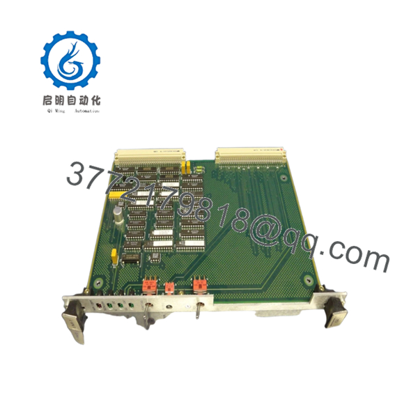
Available inventory records identify 01-W3737B-01B as a Motorola EMI-1 VMEbus module equipped with environmental monitoring functions, status indicators, and sensor power controls.
4. Product Introduction
The Motorola EMI-1 01-W3737B-01B is a VMEbus environmental monitoring module used in Motorola embedded computing platforms and VME-based industrial systems. The board provides chassis monitoring functions, sensor status indication, and environmental interface management through dedicated front-panel controls and status LEDs.
In field installations, the EMI-1 is typically paired with environmental monitoring hardware and transition modules to supervise system operating conditions. Many legacy Motorola VME systems continue to use this module because replacing an entire VME infrastructure is often considerably more expensive than maintaining spare boards.

- EMI-1 01-W3737B-01B
5. Installation & Configuration Guide
Stage 1: Pre-Installation Preparation (10 Minutes)
⚠️ Safety First
- Notify operations personnel of planned maintenance.
- Verify the controlled equipment is in a safe state.
- Apply lockout/tagout procedures.
- Remove all chassis power.
- Wait at least 5 minutes for capacitor discharge.
Tools Required
- ESD wrist strap
- PH1 screwdriver
- Fluke 115 multimeter
- Wire labels
- Smartphone for documentation
- Flashlight
Data Backup
- Export any accessible system configurations.
- Record VME slot assignments.
- Photograph front-panel settings.
- Photograph all associated transition-module connections.
- Document alarm and sensor wiring.
Stage 2: Removing the Old Module (5 Minutes)
- Open the chassis cover if required.
- Label connected wiring and sensor interfaces.
- Disconnect cables carefully.
- Release the VME ejector handles.
- Pull the board straight out from the backplane.
⚠️ Note
Retain the original module until the replacement completes a full operational test cycle.
Inspection
- Inspect VME connectors for bent pins.
- Check card guides for damage.
- Remove dust from the slot area.
- Verify associated transition modules are secure.
Stage 3: Installing the New Module (10 Minutes)
Critical Steps
- Wear a grounded ESD wrist strap.
- Verify the replacement part number is exactly 01-W3737B-01B.
- Duplicate all jumper and switch settings from the original board.
- Insert the module into the card guides.
- Seat the board fully into the VME backplane.
- Lock the ejector handles.
- Reconnect sensor and monitoring wiring.
Configuration Clone (Crucial)
This is the most common rookie mistake, but it happens constantly.
Before removing the old board, photograph every switch position, jumper, and wiring termination. Many legacy Motorola monitoring systems rely on hardware-level configuration rather than software setup.
Self-Checklist
- Part number verified
- Switches duplicated
- Wiring secured
- Board fully seated
- ESD procedures followed
- Backplane inspected
Stage 4: Power-On & Testing (10 Minutes)
Pre-Power Check
- Measure chassis power rails.
- Verify no shorts exist between power and ground.
- Confirm sensor wiring integrity.
Startup Procedure
- Power up the VME chassis only.
- Observe TMP/OFF and Sensor LEDs.
- Verify sensor power operation.
- Test chassis monitoring functions.
- Confirm alarm reporting.
- Verify communication with supervisory hardware.
⚠️ Troubleshooting Note
- Sensor LEDs not responding often indicate field wiring issues.
- Chassis monitoring faults may result from transition-module problems.
- If the board remains inactive after startup, inspect the VME backplane connectors and power rails.
6. Frequently Asked Questions (FAQ)
Q1. Can I hot-swap the EMI-1 module?
No.
The EMI-1 belongs to a traditional VMEbus architecture. Removing or inserting the board under power risks damaging both the module and the backplane. Shut down the chassis before servicing.
Q2. Is the EMI-1 obsolete?
Yes.
The EMI-1 is legacy Motorola VMEbus hardware and is no longer in OEM production. Most available inventory comes from surplus stock, tested used inventory, or decommissioned systems.
Q3. What does the EMI-1 actually monitor?
The module provides environmental interface and chassis monitoring functions. Available documentation confirms status indicators for temperature/off-state conditions and sensor monitoring, along with dedicated chassis and sensor-power controls.
Q4. Is this board available as new hardware?
Occasionally.
Most inventory currently available in the market is:
- New Surplus
- Tested Used
- Refurbished
Always request photographs, serial numbers, and test reports before purchase.
Q5. What is the direct replacement?
The safest replacement is the identical EMI-1 revision carrying part number 01-W3737B-01B.
I’ve seen engineers install a visually similar board only to discover that front-panel functions or transition-module interfaces differed enough to create commissioning delays.
Q6. Does the board require firmware matching?
In many VME systems, yes.
Even when the hardware powers up normally, differences between board revisions and supervisory software can produce unexpected alarm behavior.
Document existing hardware revisions before replacement.
Q7. Why are surplus units priced differently?
Several factors affect pricing:
- Traceability documentation
- Functional test status
- Warranty coverage
- Inventory scarcity
- Physical condition
Recent surplus listings have shown tested EMI-1 modules carrying one-year warranties from industrial automation suppliers.
Technical Pitfall & Survival Guide
❗ Firmware Revision Mismatch
I’ve seen maintenance teams spend two days troubleshooting a monitoring fault that turned out to be a revision mismatch between the replacement module and the host system.
Avoidance: Record board revision information before removal and request matching revisions when ordering.
❗ DIP Switch / Jumper Misconfiguration
This remains one of the most common causes of commissioning failures.
A single incorrect switch setting can disable monitoring functions or sensor reporting.
Avoidance: Photograph every switch and jumper before removing the original board.
❗ Terminal Block / Wiring Incompatibility
Environmental monitoring systems often include custom field wiring.
Do not reconnect cables from memory.
Avoidance: Verify every connection against the wiring diagram before applying power.
❗ Power Draw Specifications
Many legacy VME racks have accumulated upgrades over decades of operation.
Additional monitoring modules can push marginal power supplies beyond safe operating limits.
Avoidance: Verify total chassis loading and maintain at least a 20% power reserve.
❗ Electrostatic Discharge (ESD)
I once watched a technician replace an environmental monitoring board during winter without using a wrist strap. The module appeared normal until power-up, then immediately failed self-checks.
Avoidance: Always use a grounded wrist strap and ESD-safe work surface.
Keep these checks in mind and you’ll save yourself 90% of typical rework time.


