
 WhatsApp: +86 16626708626
 Email:
  Phone: +86 16626708626
Description
Key Technical Specifications
| Parameter | Value |
|---|---|
| Module Type | Multifunction rear-I/O PMC module |
| Model | IPMC761-001 |
| PMC Form Factor | Single-wide, standard-length, standard-height |
| Host Interface | 32-bit PCI through PMC P11, P12, P13, P14, and P15 |
| Required Host Slot | PMC slot 1 |
| Compatible Host Boards | MVME5100, MVME5500, MVME6100 |
| Compatible Legacy Platform | MVME2600 and MVME2700 through MVME761 transition hardware |
| SCSI Interface | One single-ended Ultra-Wide SCSI port |
| SCSI Controller | LSI Logic SYM53C895A |
| SCSI Clock | 40 MHz |
| SCSI Transfer Rate | Up to 40 MB/s synchronous transfer on 16-bit bus |
| Parallel Port | One IEEE 1284-compatible parallel port |
| Async Serial Ports | Two |
| Sync/Async Serial Ports | Two |
| Serial Controller | Z85230 ESCC with Z8536 CIO support |
| Async Serial Rate | Up to 38.4 kb/s EIA-232; up to 115 kb/s raw, depending on interface |
| Synchronous Serial Rate | Up to 2.5 Mb/s |
| PCI Signaling | 5 V |
| Onboard VPD | 256 × 8 serial EEPROM, AT24C02 |
| Power Rails | +3.3 V and +5 V through PMC connectors |
| Typical Use | IPMC mode with MVME761 rear transition module |
| S1 Function | SCSI speed and width configuration |
| S2 Function | PCI-to-ISA bridge IDSEL selection |
| Jumper Controls | J2 and J3 configure serial-port transmit-clock source |
The Motorola installation manual identifies the IPMC761 as an optional PMC module for MVME5100, MVME5500, and MVME6100 systems. It provides backward compatibility with MVME761 rear-transition hardware and must be installed in PMC slot 1.
Product Introduction
The Motorola Computer Group IPMC761-001 is a multifunction rear-I/O PMC module for legacy MVME single-board computers. It provides one single-ended Ultra-Wide SCSI port, one parallel port, two asynchronous serial ports, and two synchronous/asynchronous serial ports through compatible rear-transition hardware.
This module is used in IPMC mode with MVME5100, MVME5500, and MVME6100 host boards, preserving MVME761-style I/O in older VME control and embedded-computing systems. Verify the host board, PMC slot, S1/S2 switch settings, J2/J3 clock jumpers, transition module, and SCSI adapter before installation.
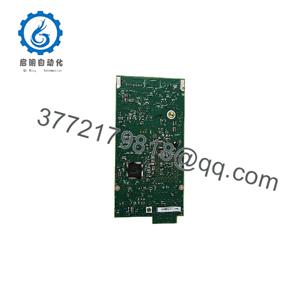
IPMC761-001
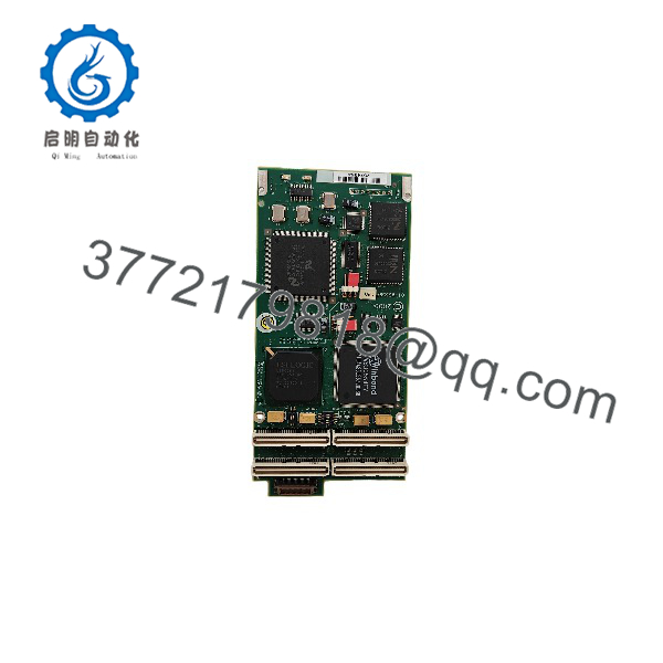
IPMC761-001
Troubleshooting Quick Reference
| Symptom | Possible Cause | Relevance to This Part | Quick Check Method | Recommendation |
|---|---|---|---|---|
| Host board does not detect the IPMC761 | Module not installed in PMC slot 1, bent PMC pins, poor connector seating, incorrect host mode | ✅ High | Power down, inspect P11–P15, reseat the module, and confirm the SBC is configured for IPMC mode | Correct slot and host configuration before replacing the module |
| MVME system fails during boot | PCI-to-ISA bridge conflict, incorrect S2 IDSEL setting, damaged PMC connector | ✅ High | Compare S2 with the host-board mapping and review PPCBug PCI enumeration | Match the S2 setting to the exact MVME5100, MVME5500, or MVME6100 host |
| SCSI device is not detected | Cable, termination, SCSI ID, S1 speed/width setting, or failed SYM53C895A controller | ✅ High | Check termination and device ID; use PPCBug or OS-level SCSI diagnostics; inspect S1 | Test the SCSI chain with a known-good cable and one known-good device |
| SCSI bus reports intermittent errors | Missing termination, excessive cable length, poor ground, marginal device | ⚠️ Medium | Run a controlled single-device test and verify termination at the physical ends of the bus | Correct the SCSI installation before changing the IPMC761 |
| SCSI operates at the wrong width or speed | S1 GPIO configuration does not match the installed bus | ✅ High | Photograph the original S1 setting and compare it with the manual’s speed/width table | Restore the correct S1 configuration before commissioning |
| Parallel port is unavailable | MVME761 transition board or P2 adapter wiring fault, incorrect IPMC mode | ⚠️ Medium | Test the port through the operating system or PPCBug and verify the MVME761 adapter | Check transition hardware and P2 routing before condemning the PMC module |
| Async serial ports do not respond | Wrong port mapping, transition-module wiring fault, baud or handshaking mismatch | ⚠️ Medium | Confirm COM1/COM2 pinout, cable type, baud rate, and loopback operation | Use a serial loopback plug and verify the rear-transition module |
| Sync/async serial port has no data | J2/J3 clock source mismatch, SIM configuration, cable or protocol mismatch | ✅ High | Check J2/J3 positions and verify whether the external device supplies or receives clock | Match clock-source jumpers to the connected equipment before replacing hardware |
| Only some serial ports work | Interface routing or transition-module limitation | ⚠️ Medium | Test each port independently at the transition module and inspect the relevant connector | Trace the signal path from P14/P15 to the before replacing the IPMC761 |
| IPMC status LEDs remain inactive | No PCI grant, host not powered, module not seated, or host-board fault | ⚠️ Medium | Check the SCSI and PIB LEDs during boot and verify host power rails | Diagnose the host PMC slot and PCI enumeration first |
| System works with IPMC712 but not | Wrong host configuration or incompatible transition module | ✅ High | Confirm the /MVME712M pairing and set the MVME host’s IPMC variant correctly | is intended for -style rear I/O; do not substitute by connector appearance |
| Fault appears after handling | ESD damage or bent PMC connector pins | ✅ High | Inspect under magnification and test on a known-good compatible host | Use a grounded wrist strap and never force the module into the PMC connectors |
Support note: Contact technical support with photographs of the -001 label, PCB revision, S1/S2 settings, J2/J3 jumpers, host-board model, transition module, boot diagnostics, and SCSI/serial test results.
Frequently Asked Questions (FAQ)
What does the Motorola -001 do?
The -001 adds legacy rear I/O to compatible Motorola MVME single-board computers. Its interfaces include Ultra-Wide SCSI, a parallel port, two asynchronous serial ports, and two synchronous/asynchronous serial ports. It is an I/O expansion module, not a standalone VME CPU.
Which host boards support the -001?
The documented host platforms are MVME5100, MVME5500, and MVME6100 boards. The module installs in PMC slot 1 and requires the host board to operate in IPMC mode. Older MVME2600 and MVME2700 systems can use the through compatible transition hardware.
Can I with an MVME712M transition module?
No. The is the -compatible variant. The IPMC712 is the variant intended for MVME712M-style I/O. The two modules have different serial-port and interface arrangements, so match the PMC module to the transition module rather than relying on physical fit alone.
a standard PCI card?
No. It uses the PMC form factor and connects to the host board through PMC P11, P12, P13, P14, and P15 connectors. It requires a compatible PMC host slot and cannot be installed in an ordinary desktop PCI slot without the correct carrier hardware.
What does the “-001” suffix identify?
The -001 suffix identifies a specific product version used with -compatible rear I/O. Do not substitute an -002 without checking the application and revision. The installation manual lists -002 as a later model, so the complete suffix and board markings should be matched during procurement.
C be hot-swapped?
No. Treat it as a powered-down PMC mezzanine module. The Motorola manual requires the module to be installed on the host board before the host board is installed in the VME chassis. Remove system power, discharge the chassis, use ESD protection, and inspect the connectors before handling.
Why is this module expensive or difficult to source?
is a legacy Motorola Computer Group part tied to obsolete MVME a761 architectures. Available units may be new surplus, pulled, used, or refurbished. Ask for the exact board revision, S1/S2 and J2/J3 settings, tested interfaces, included accessories, warranty, and return terms before purchasing.



