
 WhatsApp: +86 16626708626
 Email:
  Phone: +86 16626708626
Description
| Parameter | Specification |
| Processor | PowerPC 750 or PowerPC 740 @ 233 MHz, 266 MHz, 300 MHz, or 366 MHz |
| L2 Cache | 1 MB or 512 KB backside L2 cache |
| System Memory (RAM) | 32 MB to 1 GB ECC SDRAM via onboard mezzanine sockets |
| Flash Memory | 1 MB / 2 MB System Flash (PPCBug/OpenBoot), plus onboard Flash drive options |
| CompactPCI Bus Interface | PICMG 2.0 6U CompactPCI 32/64-bit @ 33 MHz |
| Mezzanine Expansion | 2 IEEE 1386.1 PMC (PCI Mezzanine Card) slots |
| Ethernet | 10/100Base-TX via DEC 21143 / Intel controller (RJ-45 on front panel) |
| Serial Ports | 2 RS-232 serial ports (COM1 micro-DB9 or RJ-45 on front panel, COM2 via J2) |
| Graphics Controller | Onboard Cirrus Logic CL-GD5446 or equivalent VGA controller |
| Operating System Support | VxWorks, LynxOS, QNX, Linux, Wind River |
| Operating Temperature | 0°C to +55°C (Standard industrial options available) |
| Form Factor | 6U cPCI Eurocard (single-slot or dual-slot withPMC expansion) |
The Motorola MCP750 is an industrial 6U CompactPCI single board computer designed for high-availability real-time applications in telecommunications, defense, transportation, and industrial automation. Built around the RISC-based PowerPC 750/740 processor family paired with Motorola’s Hawk PCI host bridge, it delivers deterministic processing power with low thermal overhead.
The board provides extensive I/O routing through front-panel interfaces and rear CompactPCI J2/J3/J4/J5 connectors. Featuring onboard ECC memory architecture, real-time clock, watchdog timers, and dual PMC expansion bays, the MCP750 remains a standard baseline host architecture for legacy VxWorks and LynxOS control systems.
Quality Control & SOP Transparency
Because the MCP750 is a legacy board, every unit undergoes strict 5-stage bench testing prior to dispatch to guarantee drop-in operational integrity:
- Inbound Inspection & Traceability:
- Visual audit under magnification for capacitor swelling, pin solder cracks, or board warping.
- Serial number cross-check and anti-counterfeit component verification.
- Live Functional Testing:
- Mounted in a genuine 6U CompactPCI test chassis with backplane powering.
- Execution of full PPCBug hardware diagnostics: processor register checks, L2 cache testing, L1/L2 cache integrity checks, and PCI bus enumeration.
- RAM stress testing (100% address space test with ECC error monitoring) for over 12 hours under elevated temperature.
- Communication handshake validation: Ethernet ping tests, serial COM1/COM2 transmission loops, and PMC card recognition tests.
- Electrical Parameter Testing:
- Insulation and short-circuit verification across 3.3V, 5V, +12V, and -12V rail inputs.
- Ground continuity check to backplane stiffener plates.
- Firmware & Configuration Verification:
- Read and document current PPCBug boot firmware version (e.g., V3.1/V4.0).
- Backup firmware image and verify DIP switch/jumper blocks for system controller vs. peripheral mode.
- Final QC & Packaging:
- Final sign-off by QC engineer.
- Board sealed in conductive ESD shielding, layered in high-density foam within custom heavy-duty corrugated shipping cartons.
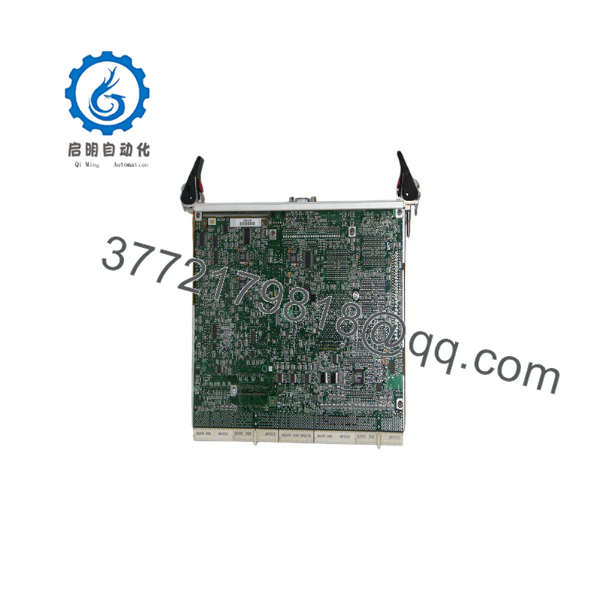
MCP750
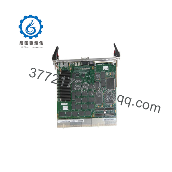
MCP750
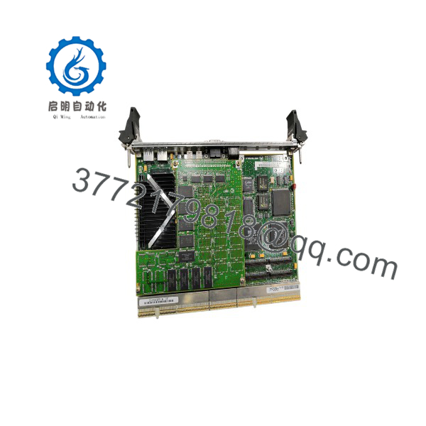
MCP750
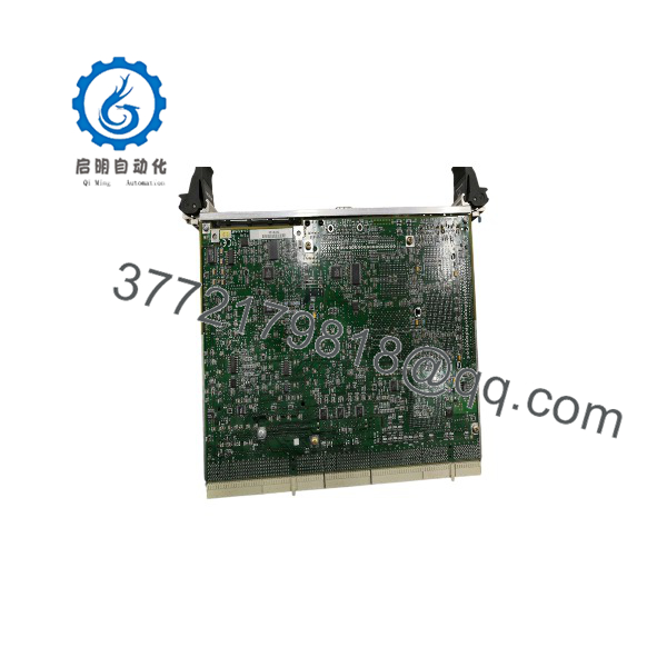
MCP750
Technical Pitfall & Survival Guide
⚠️ 1. System Controller vs. Peripheral Node Jumpering
- Issue: Installing an MCP750 configured as a System Controller into a non-slot-1 backplane position (or vice versa) halts the PCI bus enumeration, causing the chassis to stay hung at system boot.
- Avoidance: Check jumper settings for the System Controller bit (typically on header J1 or via software configuration jumpers). Ensure the board occupying Slot 1 drives the SYSEN# line.
⚠️ 2. PPCBug / Firmware Environment Variables Mismatch
- Issue: Swapping an MCP750 board without cloning NVRAM settings causes boot loop failures when loading OS kernels (VxWorks/LynxOS) over network boot (BOOTP/TFTP).
- Avoidance: Dump the NVRAM configuration via
ENVcommand in PPCBug prompt on the old board before removal. Match IP addresses, subnet masks, boot file paths, and memory map offsets on the replacement board.
⚠️ 3. ESD Damage on PMC Mezzanine Interfaces
- Issue: Inserting or removing PMC expansion cards without grounded ESD precautions damages the PCI bridge on the MCP750 mainboard.
- Avoidance: Never hot-swap PMC cards or pull the from a live cPCI backplane. Always wear a grounded ESD wrist strap when attaching or detaching PMC modules.
⚠️ 4. Backplane Power Rail Sag
- Issue: Legacy cPCI power supplies can degrade over time. An under full processing load combined with heavy PMC mezzanine cards can pull over 20W on the 3.3V/5V rails, causing soft reboots if power drops below 5%.
- Avoidance: Measure backplane voltage levels at the board connector under load. Ensure 5V DC measures between 4.85V and 5.15V DC.
Estimated Time: 20 to 30 minutes
Stage 1: Pre-Installation Preparation
- ⚠️ Safety First: Power down the CompactPCI chassis completely. Disconnect the main AC/DC power feed to the power supply unit. Wait 5 minutes for power supply filter capacitors to discharge fully.
- Tools Required: Grounded ESD wrist strap, flathead screwdriver (3.5 mm), PH1 screwdriver (for PMC standoff screws), terminal console cable (micro-DB9/RJ-45 to USB serial converter), laptop with serial terminal emulation software (19200-8-N-1).
- Data Backup: Connect serial console to old board, access PPCBug prompt (
PPC1-Bug>), runENVandGEVcommands, and log all terminal output to a text file.
Stage 2: Removing the Old Module
- Unplug front panel Ethernet, serial console, and VGA cables.
- Unfasten top and bottom card ejector handle retention screws.
- Pivot top and bottom injector/ejector handles outward simultaneously to unseat card edge connectors from the backplane.
- Slide the board straight out along the chassis guide rails. Place immediately onto an ESD mat.
- If PMC modules are installed, transfer them carefully to the replacement board using correct standoff torque.
Stage 3: Installing the New Module
- Wear grounded ESD wrist strap. Match onboard DIP switches and jumpers on the replacement board to match the original unit.
- Align the PCB edges with the guide rails of the target slot (ensure Slot 1 if configured as System Controller).
- Slide the board smoothly into the slot until the ejector levers contact the chassis rail lip.
- Press both ejector handles inward in tandem until they snap flush with the front panel, locking the board onto the backplane connectors. Tighten front panel retaining screws to 0.5 Nm.
- Reconnect serial console cable to front panel COM1 port.
- Self-Checklist: [ ] Board seated completely, [ ] DIP switch / System Controller jumper verified, [ ] Console cable attached.
Stage 4: Power-On & Testing
- Apply chassis power while monitoring terminal console output at 19200 baud.
- Verify board boots into PPCBug prompt (
PPC1-Bug>) without memory or PCI bus self-test errors. - Restore NVRAM environment variables using saved text file commands (
ENV). - Issue
G(Go) command or cycle power to boot VxWorks / LynxOS / Linux target OS. - Confirm green status LEDs on front panel, verify link LED on Ethernet port, and test system network communication.
- ⚠️ Troubleshooting Note: If no output appears on console upon power-up, check baud rate settings (default is often 9600 or 19200 baud) and confirm whether console output is directed to front panel COM1 versus rear transition module COM2.
Q: Is the Motorola hot-swappable in a live CompactPCI chassis?
A: No. Standard models do not feature full PICMG 2.1 Hot Swap silicon control logic. Attempting to pull or insert the card into an energized cPCI backplane can cause transient voltage spikes that ruin backplane traces, drive control buses into illegal logic states, or damage onboard PCI bridge chips. Always shut down power to the card slot before removal or insertion.
Q: Can I run standard x86 Linux or Windows on the ?
A: No. The is based on PowerPC RISC architecture (PPC750/740), not Intel/AMD x86 instruction sets. Operating systems must be compiled specifically for PowerPC architectures. Supported real-time operating systems include Wind River VxWorks, LynxOS, QNX, and specialized PowerPC Linux distributions.
Q: How do I access the onboard boot diagnostics and setup menu?
A: Connect an RS-232 serial cable from your PC to the front panel COM1 port (set terminal emulation software to 19200 baud, 8 data bits, no parity, 1 stop bit). Apply board power and press Break or ESC key during initial boot memory test to drop into the PPC1-Bug> command-line environment.
Q: What is the direct replacement path if my exact assembly code is out of stock?
A: The series spans several sub-part numbers based on CPU clock speed (233 MHz to 366 MHz) and onboard RAM size. In most cases, a higher clock speed or higher RAM variant of the can act as a direct drop-in replacement, provided the PPCBug boot code version matches your OS board support package (BSP).
Q: Why are your prices lower than original factory list prices for these boards?
A: We source verified new surplus stock, system decommission inventory, and enterprise spares directly from defense contractors and industrial system upgrades. Every board undergoes strict 5-stage functional testing on genuine cPCI test racks before entering inventory. You receive genuine Motorola hardware backed by our 1-year replacement warranty without waiting for OEM lead times.



