
 WhatsApp: +86 16626708626
 Email:
  Phone: +86 16626708626
Description
3. Key Technical Specifications
| Parameter | Value |
|---|---|
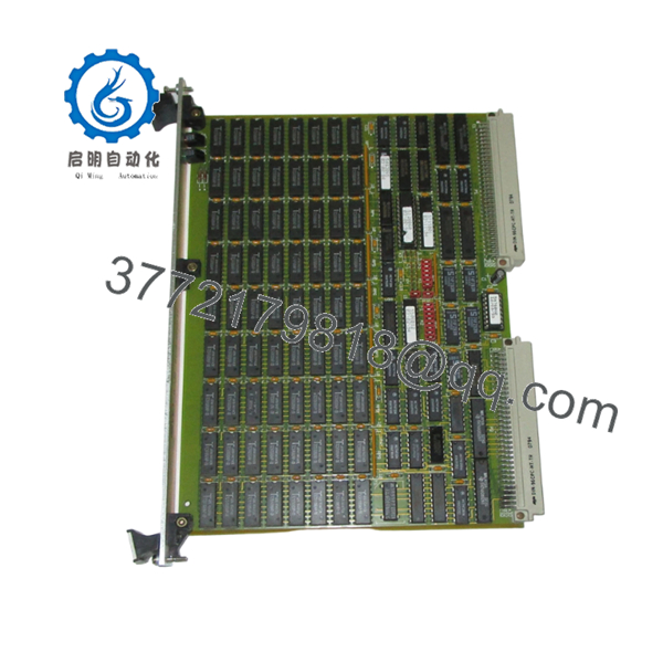
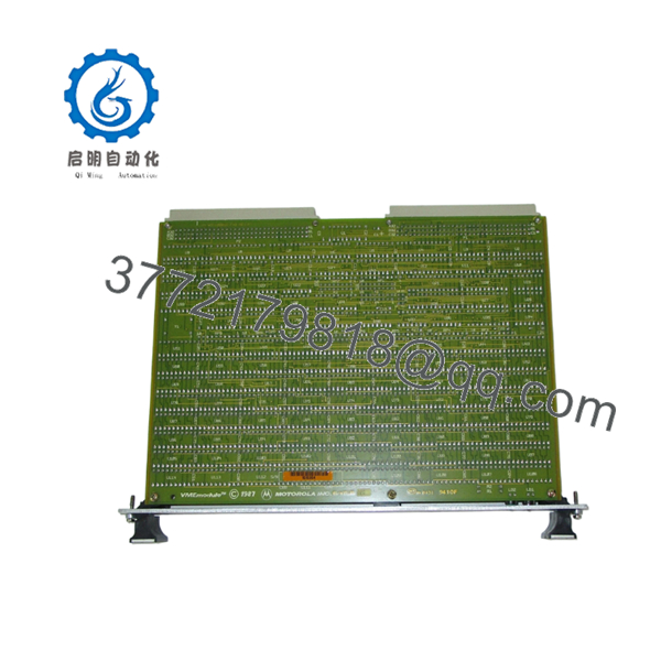
| Model Number | MVME 226-2 |
| Board Part Number | 64-W5697B01B |
| Revision | Rev. D |
| Manufacturer | Motorola |
| Product Family | MVME VMEbus Systems |
| Form Factor | VMEbus Single Board Computer |
| Bus Interface | VMEbus |
| Architecture | 32-bit Embedded Processing Platform |
| Application | Industrial Control, Test Systems, OEM Equipment |
| Installation Type | Rack-Mounted VME Chassis |
| Cooling Method | Passive Airflow / System Chassis Dependent |
| Product Status | Obsolete / Legacy Hardware |
| Typical Use Cases | Process Control, Machine Control, Legacy System Support |
The MVME226 family is part of Motorola’s legacy VMEbus computing platform used extensively in industrial automation, military systems, transportation controls, semiconductor equipment, and scientific instrumentation. The MVME226-2 variant appears in multiple legacy VME inventories and surplus equipment databases.
4. Product Introduction
The Motorola MVME 226-2 (64-W5697B01B Rev. D) is a VMEbus single-board computer designed for embedded industrial and OEM control systems. It serves as the central processing module within VME racks used for machine automation, process control, data acquisition, and specialized equipment applications.
Engineers typically select this board when maintaining installed VMEbus systems where software validation costs and downtime risks outweigh a complete platform migration. Its primary advantage is maintaining compatibility with existing VME infrastructure while avoiding costly control-system redesigns.

- MVME 226-2 64-W5697B01B Rev. D
- MVME 226-2 64-W5697B01B Rev. D
5. Installation & Configuration Guide
Stage 1: Pre-Installation Preparation (10 Minutes)
⚠️ Safety First
- Notify operations personnel of planned downtime.
- Place equipment in a safe operating state.
- Apply Lock-Out/Tag-Out (LOTO) procedures.
- Remove rack power.
- Wait at least 5 minutes for power supply capacitors to discharge.
Tools Required
- ESD wrist strap
- PH1 screwdriver
- Digital multimeter (Fluke 115 or equivalent)
- Wire labels
- Smartphone for documentation
- Flashlight
Data Backup
- Export controller software and configuration files.
- Document all network addresses.
- Photograph:
- Front panel settings
- Jumper positions
- DIP switch configurations
- Rack slot locations
- Record firmware revision if accessible.
Stage 2: Removing the Old Module (5 Minutes)
- Remove the front bezel if installed.
- Label all external connections.
- Disconnect cables carefully.
- Release VME card retainers.
- Pull the board straight outward.
⚠️ Do not rock the board side-to-side excessively. VME connectors can be damaged by uneven extraction force.
- Inspect:
- Backplane connectors
- Guide rails
- Connector pins
- Dust accumulation
⚠️ Keep the old board available until commissioning is complete.
Stage 3: Installing the New Module (5 Minutes)
Configuration Clone (Critical)
- Put on ESD protection.
- Verify:
- MVME 226-2 model number
- 64-W5697B01B assembly number
- Revision compatibility
- Copy all DIP switch settings exactly.
❗ This is the most common rookie mistake, but it happens constantly. Take a picture before you pull it. I can’t stress this enough.
- Slide the board into the guide rails.
- Engage connectors evenly.
- Secure retaining hardware.
- Reconnect all cables.
Self-Checklist
- Model numbers match
- DIP switches duplicated
- Jumpers duplicated
- Connectors seated
- Retainers secured
Stage 4: Power-On & Testing (10 Minutes)
Pre-Power Check
- Measure resistance between supply rails and ground.
- Verify no short circuits exist.
Power-Up Sequence
- Energize rack power only.
- Observe startup LEDs.
- Verify normal boot sequence.
- Connect service terminal or engineering workstation.
- Confirm communication with system software.
- Verify firmware revision.
- Restore configuration if required.
- Test I/O functions.
Basic Functional Test
- Verify rack communication.
- Verify VMEbus access.
- Check watchdog operation.
- Confirm field device response.
- Monitor for thermal abnormalities.
⚠️ Troubleshooting Note:
- Solid fault LED → suspect firmware mismatch.
- No communication → check slot position, addressing, and jumper settings.
- Intermittent faults → inspect backplane connector wear.
6. Frequently Asked Questions (FAQ)
Q1. Can I hot-swap the MVME 226-2 while the rack is powered?
No.
Most legacy VME systems using the MVME226 family were not designed for hot insertion. Removing or inserting the board under power can corrupt bus transactions or damage the backplane. Shut down the rack first.
Q2. Is the MVME 226-2 obsolete?
Yes.
This is a legacy Motorola VMEbus platform that has been out of mainstream production for many years. Availability is generally limited to surplus inventory, tested used units, or refurbished stock.
Q3. Is the board genuinely new?
That depends on inventory source.
For legacy VME hardware, “New Original” typically means unused surplus stock that remained in OEM or distributor inventory. Always request board photos, serial labels, and inspection reports before purchase.
Q4. Will I lose my application software when replacing the board?
Usually no, but verify first.
In many installations, application software resides on external storage or is backed up through engineering software. Before pulling the old module, archive all software and configuration files.
I’ve seen maintenance teams assume everything was stored elsewhere, only to discover a custom boot image existed exclusively on the failed board.
Q5. What should I check before ordering a replacement?
Verify:
- Model number (MVME 226-2)
- Assembly number (64-W5697B01B)
- Hardware revision (Rev. D)
- Firmware revision
- VME slot location
- Operating system compatibility
Firmware mismatch is one of the most common causes of commissioning delays.
I’ve seen projects where a technician swapped in a newer board and spent two days chasing communication alarms. The issue turned out to be a firmware revision difference.
Q6. Why is surplus pricing often lower than OEM historical pricing?
Because OEM support has ended.
Most available units come from decommissioned systems, excess inventory, or certified surplus channels. Pricing reflects market availability rather than original factory list pricing.
Q7. What are the biggest installation risks?
The top five are:
- Firmware revision mismatch
- Incorrect DIP switch settings
- Wrong slot location
- Connector pin damage
- Electrostatic discharge (ESD)
I once watched an engineer unpack a VME CPU board during winter without an ESD strap. The board never booted again. That mistake cost more than the maintenance window itself.
❗ Keep these checks in mind and you’ll save yourself 90% of typical rework time.


