WhatsApp: +86 16626708626
 Email:
 Phone: +86 16626708626
Description
3. Key Technical Specifications
- CPU: Motorola MC68010, 10 MHz, 16/32-bit internal architecture
- Memory: 2 MB onboard DRAM (with parity), expandable via VMEbus
- Bus Interface: VMEbus (IEEE 1014), P1 and P2 connectors, master/slave capable
- Serial I/O: 2 × RS-232-C ports (via front-panel transition or P2)
- Timers: Programmable interval timers (3-channel)
- Real-Time Clock: Battery-backed RTC (verify battery condition before deployment — see pitfalls)
- Parallel I/O: 8-bit parallel port with handshake support
- Interrupts: VMEbus interrupt handler, 7-level priority scheme
- Board Format: Single-height (1-slot) 6U VME card, double-sided Eurocard
- Operating Voltage: +5 V DC from VMEbus backplane (±12 V rails for serial I/O)
- Operating Temperature: 0 to +50 °C (typical for MVME68K era boards)
- Typical Current Draw: ~3–5 A at 5 V (confirm against your chassis power budget)
4. Product Introduction
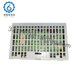
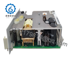
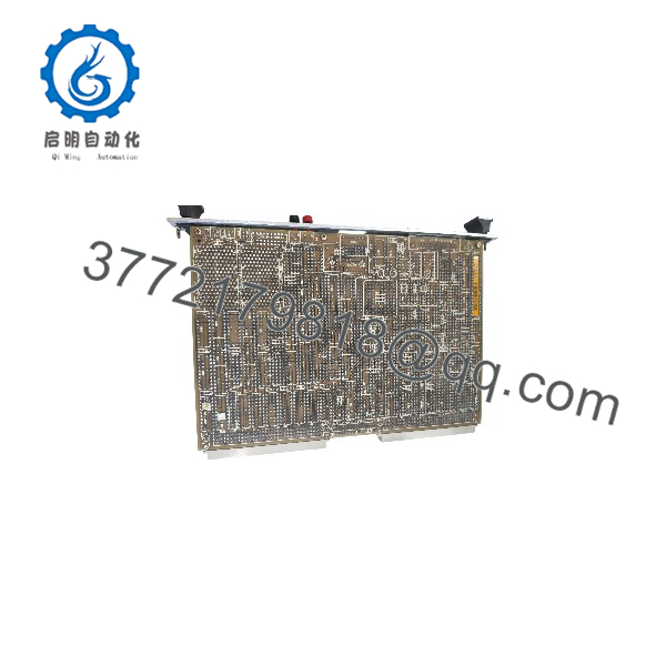
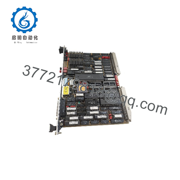
The Motorola MVME117A is a single-board VMEbus computer built around the MC68010 processor running at 10 MHz with 2 MB of onboard DRAM. It serves as the CPU/controller card in legacy industrial control systems, test fixtures, and embedded automation racks that were designed around the MVME100 series architecture.
Plants keep buying this board for one reason: the surrounding system still works, and rewriting a proven 68K-based control application costs far more than a replacement CPU card. It drops into an existing MVME117/117A slot with no software changes, provided you match the board revision and EPROM contents to your original unit. Verify the exact assembly number (01-W3472B01B) and firmware/EPROM version against your installed board before ordering.
5. Troubleshooting Quick Reference
| Symptom | Possible Cause | Relevance to this Part | Quick Check Method | Recommendation |
|---|---|---|---|---|
| No LEDs / dead board | Backplane +5 V missing, blown slot fuse | ❌ Low | Measure +5 V at P1 pin 32 with a Fluke 115; check chassis PSU | Fix power and fuses before blaming the board |
| Board boots but no VMEbus response | VMEbus arbitration jumper or EPROM version mismatch | ⚠️ Medium | Compare jumper positions against your old board; verify EPROM labels match | Mirror old board’s jumper map exactly; swap EPROMs if revisions differ |
| Random memory parity errors | Marginal DRAM or aging solder joints | ✅ High | Run a full memory test from the MVME117 debugger (117Bug) at power-up | If parity errors repeat on our board under test, we replace it — report with logs |
| Serial terminal gets garbage | RS-232 baud/parity mismatch or ±12 V rail issue | ⚠️ Medium | Loop-back test each port; verify baud DIP settings against console config | Correct baud settings first; port config error is far more common than hardware failure |
| RTC loses time/date on power cycle | Dead lithium backup battery | ✅ High (common, minor) | Check battery voltage (>2.8 V typical); look for corrosion near holder | Replace the battery — do not return the board for this; leakage damage is the real risk |
| System hangs under load | Marginal chassis PSU brownout, multiple boards sharing 5 V rail | ❌ Low | Measure 5 V ripple under load; calculate total backplane draw +20% margin | Upgrade PSU or redistribute boards; this board draws what it draws |
A note from the bench: these boards fail less often than people think. In my experience, 7 out of 10 “dead MVME117A” returns come back testing fine — the real problem was a jumper mismatch, a dead slot, or someone seating the board with the chassis still powered. If you’re stuck, email technical support with photos of the jumpers, serial port settings, and the power-up console output. We’ll tell you straight whether it’s the board or your rack.
MVME117A
MVME117A
6. Frequently Asked Questions
Q1: Is this board new, used, or refurbished?
We stock both New Surplus (factory-original, never deployed, often in original Motorola packaging) and refurbished units. Every unit — new or refurb — goes through the same test sequence: power-up on a genuine VMEbus chassis, 24-hour continuous run with thermal monitoring, full memory test via 117Bug, and serial port loop-back verification on both RS-232 channels. Test photos and video are available on request. If you specifically need New Surplus, say so at order time; stock of true NOS units of a board this old is thin.
Q2: Why is this board obsolete, and can I still get it?
Motorola exited this product line decades ago (the MVME family later moved to Freescale, then NXP). The MVME117A has no factory support and no new production — full stop. Availability is limited to surplus and refurbished stock worldwide, and that pool only shrinks. If you’re maintaining a system built on this board, I’d honestly recommend buying a spare before you need it, not after.
Q3: Will this board be a drop-in replacement for my existing MVME117 or MVME117A?
Same family, yes — but verify three things before you pull the old card: (1) the exact assembly number on the silkscreen (01-W3472B01B vs. other revisions), (2) the EPROM firmware version — 117Bug revisions changed debug register behavior, and (3) jumper configuration for VMEbus arbitration and serial port defaults. Take a photo of the old board’s jumpers before removal. A MVME117 and a 117A can behave differently in the same rack if your software assumes specific revision behavior. Verify against the Motorola MVME117A User’s Manual for your hardware revision.
Q4: Do I lose my program or configuration data when I swap the board?
Your application lives in EPROM and off-board storage, not in the CPU board itself, so a board swap does not lose the program — as long as you move your application EPROMs to the new board or your new board’s EPROMs match. But here’s the rookie trap: the onboard DRAM is volatile, so anything running purely in RAM is gone at power-down regardless. Document your EPROM part numbers and jumper positions before the swap. I’ve seen a tech lose two days because he didn’t photograph the EPROM positions and reseated them in the wrong sockets.
Q5: Can I hot-swap this board?
No. Absolutely not. The original VMEbus has no hot-swap specification — that arrived with VME64x decades after this board was designed. Pulling this card live can fry the backplane drivers, corrupt other boards’ bus cycles, or damage the board itself. Power down the chassis, wait for capacitors to discharge, ground yourself with an ESD wrist strap, then handle the board by its edges. I once watched a $2,000 card let the magic smoke out because a guy swapped boards in a dry equipment room in winter, no strap. Don’t be that guy.
Q6: What about the backup battery — should I replace it?
Yes, proactively. These boards carry an aging lithium cell for the RTC and possibly NVRAM contents. A cell sitting for 20+ years is on borrowed time, and a leaking battery corrodes the board beyond economical repair. Our tested units ship with battery voltage measured and documented; corroded boards don’t pass our inbound inspection. If your application stores calibration data in NVRAM, back it up before any swap.
Q7: What warranty and lead time do you offer?
Tested units ship with a 1-year replacement warranty covering functional failure under normal use — not physical damage, battery leakage after receipt, or mishandling like hot-swapping. In-stock boards ship within 1–2 business days via DHL/FedEx worldwide. Out-of-stock configurations typically take 2–4 weeks. Confirm stock and lead time with your sales contact before committing to a shutdown window — I’d rather tell you “3 weeks” today than have your line down waiting on a card nobody has.