
 WhatsApp: +86 16626708626
 Email:
  Phone: +86 16626708626
Description
3. Key Technical Specifications
- Processor: Motorola 68020, 32-bit microprocessor
- Clock Speed: 16–25 MHz (variant dependent)
- Coprocessor Support: Optional 68881 / 68882 FPU
- Memory: Onboard DRAM (typically 4–16 MB, configurable)
- Bus Interface: VMEbus (ANSI/IEEE 1014-1987 compliant)
- I/O Interfaces: Serial ports (RS-232), parallel I/O
- Operating System Support: VxWorks, OS-9, pSOS (legacy RTOS)
- Form Factor: 6U VME single-slot board
- Power Requirements: +5 V DC (typical VME backplane supply)
- Operating Temperature: 0 to +55 °C (industrial variants may differ)
- Connector Type: DIN 41612 VMEbus connectors
- Weight: Approx. 0.5–0.8 kg
4. Product Introduction
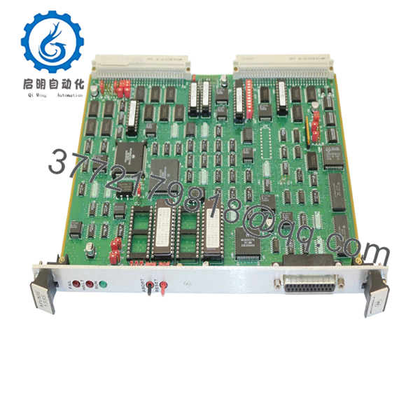
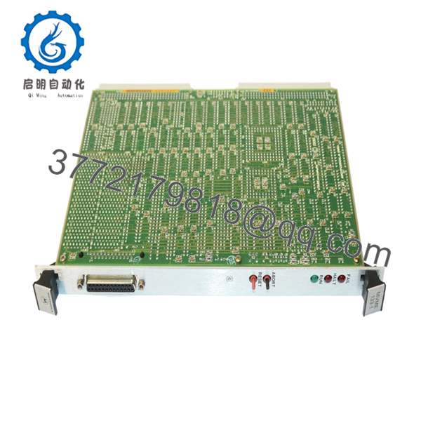
The Motorola MVME133-1-B -36271 is a 6U VMEbus single-board computer built around the Motorola 68020 processor, designed for industrial control, telecom switching, and legacy embedded systems. It functions as the central processing unit in VME-based architectures, handling real-time control and communication tasks.
In field deployments, these boards are still used in long-life systems where requalification costs exceed hardware replacement. Engineers choose this model for its proven stability under legacy RTOS environments and compatibility with existing VME backplanes without requiring redesign.

- MVME133-1-B -36271
- MVME133-1-B -36271
5. Installation & Configuration Guide
Stage 1: Pre-Installation Preparation (10–15 minutes)
- ⚠️ Safety First: Notify operations, shut down system, lock out/tag out power. Wait 5 minutes for full discharge.
- Tools Required: ESD wrist strap, flat/PH1 screwdriver, multimeter, labels, smartphone
- Data Backup:
- Backup RTOS image (VxWorks/pSOS) from storage
- Record memory map and base address settings
- Photograph jumper settings and VME slot position
Stage 2: Removing the Old Module (5–10 minutes)
- Remove rack front panel or enclosure cover
- Label all external I/O and serial connections
- Unscrew front panel retainers
- Pull the board straight out using ejector handles
- Inspect VME backplane connectors for bent pins or debris
- ⚠️ Note: Keep the original board accessible. You may need it to verify jumper settings or firmware ROM versions.
Stage 3: Installing the New Module (10 minutes)
- ESD Protection: Wear grounded wrist strap
- Verify Model: Confirm MVME133-1-B -36271 matches exactly
- Configuration Clone (Critical):
- Match all jumper settings (CPU clock, memory config, base address)
- Replicate any FPU configuration if installed
- Insert board into correct VME slot using guide rails
- Seat firmly until connectors fully engage
- Tighten front panel screws
- Self-Checklist:
- Jumpers match
- Board fully seated
- No loose cables
Stage 4: Power-On & Testing (10–20 minutes)
- Pre-Power Check: Verify +5 V rail stability with multimeter
- Power-On Steps:
- Power VME rack only
- Observe board LEDs (if equipped)
- Connect via serial console (typically 9600 baud)
- Confirm boot monitor prompt
- Load OS image if required
- Validate VME bus communication
- ⚠️ Troubleshooting Note:
- No boot: Check ROM firmware version compatibility
- Bus errors: Verify address jumper settings
- Serial no output: Check baud rate and cable pinout
6. Frequently Asked Questions (FAQ)
Q1: Can I hot-swap the MVME133 board?
No. This is not designed for hot-swapping. Removing it under power risks backplane damage and undefined bus states. Always shut down fully.
Q2: Is this unit truly new if the model is obsolete?
Yes, but it’s new surplus. That means unused OEM stock stored long-term. Packaging may not be factory sealed, but components show no signs of prior installation.
Q3: What’s the closest replacement if this is unavailable?
There’s no drop-in modern equivalent. Later models like MVME162 or MVME167 use different CPUs (68040) and may require firmware and OS changes. Verify software compatibility before considering upgrades.
Q4: Will I lose my application when replacing the board?
Depends on your system architecture. If the OS and application are stored on external storage (e.g., VME disk or EEPROM), you’re fine. If stored locally, you must back it up before removal.
Q5: Why do these boards fail after long storage?
Electrolytic capacitors age, and socketed ICs can develop poor contact. I’ve seen boards fail on first power-up after 15 years in storage. That’s why burn-in testing matters.
Q6: Why is pricing inconsistent across suppliers?
Supply is limited and condition varies widely. Some units are pulled and untested. Others are fully verified with burn-in testing. Always ask for test reports and photos.
Q7: What should I verify before installation?
- Firmware/ROM version
- Jumper configuration
- Power supply capacity
- Backplane condition
Keep these checks in mind and you’ll avoid most field failures and unnecessary downtime.


