
 WhatsApp: +86 16626708626
 Email:
  Phone: +86 16626708626
Description
Key Technical Specifications
| Parameter | Specification Value |
|---|---|
| Catalog Number | MVME133SA |
| Processor (CPU) | Motorola MC68020 32-Bit Microprocessor @ 20 MHz |
| Math Coprocessor (FPU) | Motorola MC68881 Floating Point Coprocessor @ 20 MHz |
| Bus Interface | Standard VMEbus (IEEE 1014), A32/D32 Master and Slave capabilities |
| On-Board RAM | 4 MB Dual-Ported Dynamic RAM with Parity Protection |
| ROM/EPROM Capacity | 2 x 28-pin JEDEC sockets for up to 256 KB Boot EPROM/Flash |
| Serial Ports | 4 x RS-232-C Asynchronous Communications Ports (MC68681 DUARTs) |
| Timer / Counters | 2 x Multi-Mode Programmable Timers, 1 x Watchdog Timer |
| Power Consumption | +5 V DC @ 3.5 A (Typical); ±12 V DC required for serial line drivers |
| Form Factor | Double-Height Eurocard (6U VMEbus format, 160 mm x 233.4 mm) |
| Operating Temperature | 0°C to 55°C (32°F to 131°F) operating range |
| System Controller Functions | VMEbus Arbiter (Option-Selectable), Bus Timeout Monitor, Reset Generator |
Product Introduction
The Motorola MVME133SA is a legacy 32-bit single-board computer built on the VMEbus (IEEE 1014) standard. Driven by a 20 MHz MC68020 microprocessor paired with an MC68881 floating-point coprocessor, this board provides processing performance, hardware math acceleration, and high-density memory for real-time control, defense automation, industrial robotics, and power utility sub-rack applications.
Featuring 4 MB of dual-ported DRAM with parity checking, four RS-232 serial channels, and on-board VMEbus system controller capabilities, the MVME133SA operates seamlessly as either a standalone primary master or a processing node in multi-CPU VME chassis. Designed for extreme long-term field stability, it offers full hardware backward-compatibility for legacy system maintenance, ensuring zero redesign costs when keeping critical legacy sub-assemblies running.
Troubleshooting Quick Reference
| Symptom | Possible Cause | Relevance to this Part | Quick Check Method | Recommendation |
|---|---|---|---|---|
| FAIL LED Lit Red on Boot | Power supply rail out of tolerance or DRAM parity error | ✅ High | Measure +5V and ±12V rails at the VME backplane pins with a multimeter; check parity jumper configuration. | Verify system power supply output before replacing board hardware. |
| VME Bus Access Timeout (BERR) | Incorrect slot placement or missing VME system controller | ❓ Medium | Ensure the board is in Slot 1 if acting as VME System Controller, or check system bus grant jumpers. | Set BG/IACK jumpers correctly or move the board to Slot 1. |
| No Serial Debug Console Output | Terminal baud rate or RS-232 null-modem pinout error | ❌ Low | Scope TX pin on serial port 1 (MC68681 DUART output) while toggling board reset button. | Verify terminal setting is 9600-8-N-1 and confirm cable DB-25/DB-9 wiring. |
| System Freezes Intermittently | Thermal overheating or dried-up decoupling capacitors | ✅ High | Check CPU heatsink temperature and inspect SMD tantalum/electrolytic caps for leakage. | Replace thermal pad or clean/re-cap legacy board if heat stress is observed. |
| EPROM Boot Failure | Socketed EPROM pin oxidation or corrupted firmware image | ✅ High | Reseat 28-pin EPROM chips in sockets J1/J2; verify checksum on an EPROM programmer. | Clean socket contacts with isopropyl alcohol or re-burn firmware EPROMs. |
Note: If your VME chassis continues to drop bus requests, provide your jumper map and bus monitor logs to our technical support team for diagnostic verification.
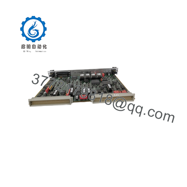
MVME133SA
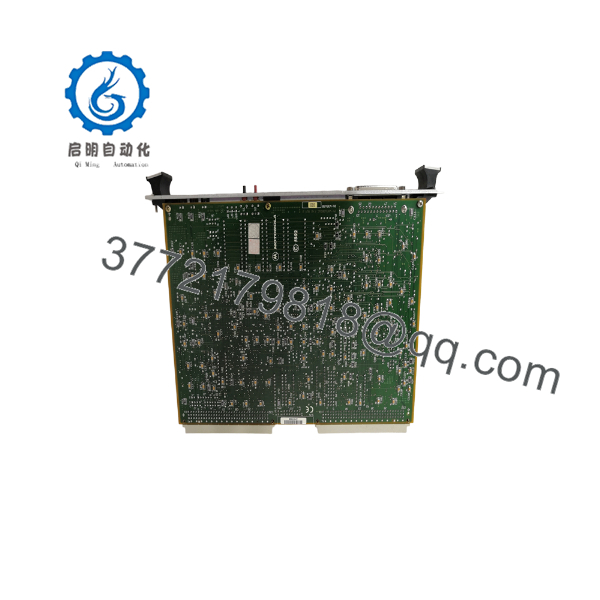
MVME133SA
Frequently Asked Questions (FAQ)
Q: What is the primary difference between the MVME133 and the MVME133SA?
A: The “SA” variant designates an updated revision featuring a faster 20 MHz MC68020 CPU and matching MC68881 FPU (compared to 12.5 MHz or 16 MHz on standard base models), paired with 4 MB of integrated dual-ported DRAM rather than the smaller 1 MB memory base found on early production releases.
Q: Does this board have to be installed in Slot 1 of the VME chassis?
A: Only if you intend for the MVME133SA to act as the VMEbus System Controller (providing bus arbitration, reset timing, and system clock functions). If another card in your rack serves as the primary controller, disable the MVME133SA system controller jumpers and install it in any available 6U VME slot.
Q: Can I run standard VxWorks or OS-9 real-time operating systems on this module?
A: Yes. The was historically the benchmark architecture for VxWorks, OS-9, and Motorola 133Bug firmware environments. Make sure your boot ROMs contain the appropriate board support package (BSP) matching the 20 MHz clock speed and memory address map.
Q: How are DIP switches and jumpers configured for address space allocation?
A: Address decoding for local memory, VMEbus window offsets, and system controller functions is handled via physical header jumpers located near the P1 backplane connector. We supply a complete factory jumper configuration table with every shipped board to ensure proper alignment with your target system.
Q: Is this board original OEM Motorola stock?
A: Yes. All units are original Motorola factory-manufactured boards. Because these legacy boards are out of production, we supply both New Surplus (unused original spares) and Refurbished boards that have been component-level inspected, recapped where necessary, and bench-tested in an active 6U VME chassis.
SOP Quality Control Process
1. Inbound Inspection & Traceability
- Verification of Motorola original component markings, serial numbers, and PCB revision codes.
- Visual audit under magnification for bent DIN 41612 connector pins, PCB solder mask oxidation, and socket pin integrity.
- Inspection of socketed ICs (MC68020, MC68881, EPROMs) to rule out lead corrosion or counterfeit marking.
2. Live Bench & Functional Testing
- Inserted into a calibrated 6U VME chassis powered by a heavy-duty regulated VME power supply.
- Boot testing using 133Bug monitor diagnostics via serial console port.
- 24-hour continuous burn-in memory test executing full 4 MB dual-port DRAM read/write cycles and parity checks under elevated ambient temperatures.
- VMEbus master/slave arbitration cycles validated across the P1 and P2 backplane connectors.
3. Electrical Parameter & Safety Checks
- Measure current draw on +5V, +12V, and -12V DC power buses under maximum operational load.
- Ground plane continuity and trace impedance verified using a Fluke 115 multimeter.
4. Firmware & Configuration Verification
- Boot EPROMs read, checksummed, and backed up.
- On-board jumper configurations cataloged and set to standard factory defaults or matched to customer specifications.
5. Final QC & Packaging
- Anti-static treatment applied; sealed inside a moisture-barrier ESD bag with active desiccant.
- Encased in high-density anti-static foam inside a double-walled corrugated shipping box.
- Serialized QA Pass certificate enclosed with the board.
Technical Pitfall & Survival Guide
- ❗ VMEbus Backplane Jumper Trap: VMEbus backplanes require physical bus grant (BG0-BG3) and IACK daisy-chain jumpers on unused slots between cards. If you remove an old board and insert the without ensuring daisy-chain continuity across empty slots, downstream boards will hang waiting for bus grant signals.
- ❗ DIN Connector Pin Damage: The 96-pin DIN 41612 P1/P2 connectors on legacy VME cards are susceptible to pin bending if inserted at an angle. Always line up card guides precisely and use the front panel ejector handles to seat the board—never force or hammer a VME card into the backplane.
- ❗ Serial Line Voltage Mismatch: The uses true RS-232 signal levels requiring ±12V DC from the VME backplane. If your VME power supply fails to deliver the ±12V rails, the board may boot, but serial communication on all four DUART ports will drop offline entirely.
- ❗ ESD Hazard on Legacy CMOS Chips: Legacy Motorola 68k family ICs are highly sensitive to static discharge. Always handle the board while wearing a grounded ESD wrist strap at a grounded workbench. Never touch edge-connector contacts or IC pins directly with bare hands.



