
 WhatsApp: +86 16626708626
 Email:
  Phone: +86 16626708626
Description
3. Key Technical Specifications
| Parameter | Specification Value |
| Manufacturer | Motorola (Embedded Computing Division) |
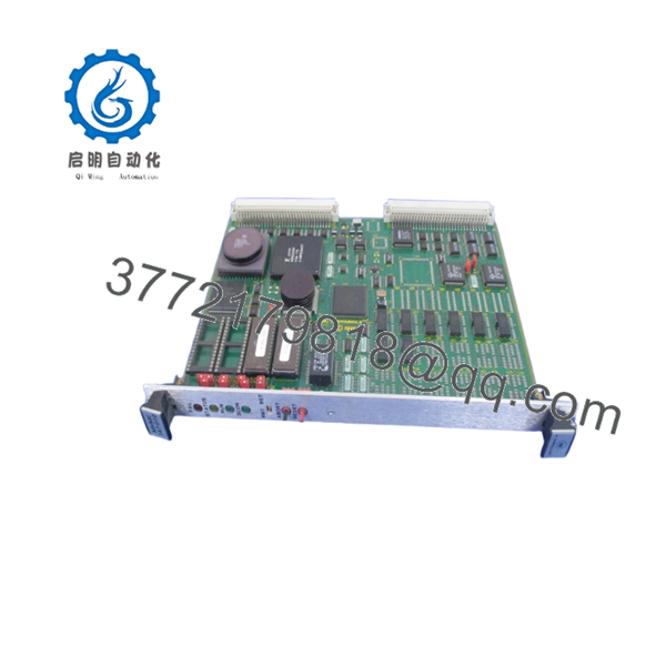
| Model Number | MVME147-010 |
| Microprocessor | MC68030 32-bit Enhanced Microprocessor |
| Floating-Point Coprocessor | MC68882 Floating-Point Coprocessor (FPU) |
| Onboard DRAM | 4 MB Shared Dynamic RAM with Parity Protection |
| Bus Interface | Master/Slave VMEbus Interface (A32/D32, A24/D16, A16) |
| System Controller Capabilities | Multi-mode VMEbus System Controller with Arbiter |
| Peripheral Interfaces | 4 Serial Ports (RS-232-C), 1 Centronics Parallel Port |
| Network Interface | Ethernet Interface (Transceiver Controller) |
| Storage Interface | SCSI Bus Interface with DMA Controller |
| Onboard Timer Functions | Real-Time Clock (RTC) and Tick Timers with Battery Backup |
| Power Consumption | +5 V DC (approx. 5.0 A to 6.5 A based on config) |
4. Product Introduction & Supply Chain Strategy
The Motorola MVME147-010 is a foundational 32-bit VMEbus single board computer built around the Motorola MC68030 microprocessor and MC68882 floating-point unit. Equipped with 4 MB of shared onboard parity DRAM, integrated SCSI controllers, and dedicated Ethernet interfaces, this board serves as the core computing backbone for high-availability legacy systems. It provides deterministic, real-time data processing and backplane arbitration across critical infrastructure networks, defense simulators, maritime controls, and process industrial facilities globally.
Maintaining the continuous operation of lines relying on the MVME147-010 demands a proactive procurement framework focused on Total Cost of Ownership (TCO). Because this hardware has been completely phased out by the OEM, finding authentic New Surplus parts is crucial for mitigating the threat of obsolete stock-outs. Settling for second-hand or poorly repaired alternatives exposes your automated systems to hidden component degradation, like dried out capacitors or weakened trace paths. Securing factory-sealed, unused surplus components ensures reliable field operation for another 10 to 15 years, shielding your facility from unpredictable downtime expenses.

- MVME 147-010
- MVME 147-010
5. Installation & Configuration Guide
Stage 1: Pre-Installation (Prep & Safety)
- Implement strict lock-out/tag-out (LOTO) procedures on the subrack power supply.
- Confirm that the main chassis power switches are completely turned off.
- Strap on a properly grounded, anti-static ESD wristband prior to removing the card from its static shielding.
- Use a camera to document the position of every jumper block (such as J1 through J22) on the existing module to facilitate an identical layout configuration.
Stage 2: Removal
- Unfasten the top and bottom mounting panel screws holding the module to the rack rails.
- Press the ejector handles outward to safely disconnect the physical backplane assembly.
- Gently slide the module outward along the plastic guide channels.
- Maintain a straight horizontal or vertical vector to avoid any side-to-side stress that could distort or damage the high-density backplane connector pins.
Stage 3: Installation (Clone & Seat)
- Adjust the jumper configurations on the new MVME147-010 board to perfectly match the original system architecture settings.
- Position the edges of the printed circuit board neatly within the upper and lower track guides of the intended slot.
- Smoothly push the assembly in until the rear pins make light contact with the chassis backplane.
- Close the card injector levers tightly to fully secure the socket connection, then tighten the panel screws.
Stage 4: Power-On & Testing
- Inspect the rack power distribution terminals with a multimeter to guarantee no direct shorts exist across the voltage lanes.
- Boot up the subrack system and check the front-panel status lights.
- Verify that the red “FAIL” LED remains dark while the green “RUN” LED lights up continuously following initialization.
- Establish a terminal handshake via the serial debug port to verify that the system successfully completes its basic input/output system boot sequences.
6. Firmware/Software Versions & Upgrade Notes
The MVME147-010 board depends on ROM-resident firmware (typically the MVME147Bug system debugger/monitor) to complete its hardware self-test routines and execute bootstrap loaders for real-time operating systems like VxWorks or OS-9. It is highly recommended to confirm that the EPROM chips mounted on your replacement unit carry the exact same firmware revision code as your old board.
⚠️ CRITICAL WARNING: Any disparity in firmware editions can lead to hardware-software integration failures, unexpected driver runtime faults, or non-volatile RAM storage reading errors. Do not run any automated flashing routines or attempt to clear the battery-backed NVRAM parameters unless you have explicitly mapped out your previous driver configurations. If your process requires a specific older system version, carefully transfer the working EPROM chips from your old core onto the new replacement module using an ESD-protective DIP extraction tool.
7. Frequently Asked Questions (FAQ)
What exactly distinguishes this MVME147-010 module from a refurbished card?
This product is a Brand New Surplus unit. It is not used, not pulled from a decommissioned plant, and not refurbished. All modules undergo rigorous quality verification to ensure OEM-level reliability. The board has never seen continuous run-time hours, displays zero pin wear, and contains no aftermarket wiring modifications or component re-soldering.
Why is purchasing a New Surplus module safer than a cheaper used option?
While a used module can offer short-term savings, refurbished parts often suffer from hidden failure vectors like degraded capacitors or thermal fatigue that cosmetics hide. If an aged component fails in production, the ensuing emergency shutdown can cost ten times what was initially “saved.” Buying a New Surplus unit secures a fresh 10–15 year component lifespan.
Does this board include the onboard battery for parameter memory retention?
Yes, the board includes integrated battery backup paths designed to preserve timekeeping functions and crucial configuration parameters in the non-volatile RAM. Because this is a New Surplus item that has been held in storage, our technical staff checks the voltage level of the onboard real-time clock battery during our standardized quality inspection process to guarantee complete data retention capabilities.
Can the MVME147-010 single board computer be inserted into any VME slot?
If you are configuring the board to operate as the primary VMEbus System Controller (handling bus arbitration and clock distribution), it must be installed in Slot 1 of the chassis backplane. If your system architecture uses a separate primary controller, the jumpers on this card must be adjusted to slave mode before placing it into any subsequent peripheral slots.
What kind of warranty do you provide for an obsolete component like this?
To provide total peace of mind for legacy system infrastructure managers, we cover this New Surplus MVME147-010 module with our comprehensive 1-year replacement warranty. If any operational errors or hardware defects appear under normal usage, we will replace the unit or provide a full credit.


