WhatsApp: +86 16626708626
 Email:
 Phone: +86 16626708626
Description
Key Technical Specifications
| Parameter | Specification |
|---|---|
| Board model | MVME147-013 |
| CPU | MC68030 |
| CPU clock | 25 MHz |
| Floating-point processor | MC68882, 25 MHz |
| Main memory | 16 MB DRAM |
| Memory parity | Supported |
| VMEbus interface | A32/D32 master/slave interface |
| Serial communications | 4 EIA-232-D ports |
| Parallel I/O | Centronics-compatible printer port |
| SCSI | Onboard SCSI interface with DMA |
| Ethernet | Onboard Ethernet transceiver interface |
| Timers | Two 16-bit timers and watchdog timer |
| Firmware | Onboard debugger and diagnostic firmware |
| Transition module | Optional MVME712-series hardware, depending on required external connections |
The model-specific configuration is 25 MHz and 16 MB DRAM. Some distributor pages describe the full MVME147 family rather than only the -013 variant, so family-wide processor and memory ranges should not be mistaken for the specifications of this specific model.
Product Introduction
The Motorola MVME147-013 integrates processing, memory, serial I/O, parallel output, SCSI storage connectivity, and Ethernet into a single VMEbus board. Its MC68030 processor and MC68882 floating-point coprocessor support legacy embedded computing applications where the existing hardware architecture and software environment must remain in service. The board’s VMEbus master/slave capabilities also allow it to participate in systems built around a compatible VME backplane.
For replacement projects, matching the part number alone is not enough. Verify the installed board revision, memory configuration, transition-module arrangement, VMEbus system-controller settings, and software dependencies. If the application relies on legacy boot firmware or SCSI peripherals, those components should be included in the compatibility assessment before the replacement board is installed.
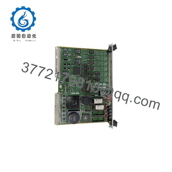
MVME147-013
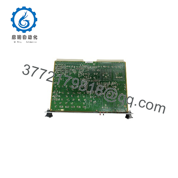
MVME147-013
Installation and Configuration Guide
Estimated time: 45–90 minutes for a straightforward replacement when the system documentation and compatible hardware are available. Legacy software recovery or interface troubleshooting may take longer.
Stage 1 — Confirm system compatibility
- Verify that the chassis and backplane support the MVME147 VMEbus board.
- Confirm the target configuration is 25 MHz with 16 MB DRAM.
- Check whether the system uses an MVME712-series transition module for external serial, parallel, Ethernet, and SCSI connections.
- Review the existing board’s firmware, boot settings, and attached peripherals before removing it.
Stage 2 — Prepare for installation
- Shut down the equipment and isolate power according to the system maintenance procedure.
- Apply electrostatic-discharge precautions.
- Record cable positions, jumper settings, and board identifiers.
- Inspect the replacement board and backplane connector for damage or contamination.
Safety note: Do not remove or install the board under power unless the complete system documentation explicitly permits it.
Stage 3 — Install the board
- Check the board’s configuration jumpers against the host-system requirements.
- Insert the board into the designated VMEbus slot, following the chassis manufacturer’s insertion procedure.
- Secure the board and reconnect the appropriate transition-module and peripheral connections.
- Verify that the VMEbus system-controller configuration is correct for the system. Do not enable the controller function indiscriminately if another board is assigned that role.
Stage 4 — Test and commission
- Power up the system and observe its documented startup and diagnostic indications.
- Verify processor initialization and access to the expected memory configuration.
- Test the serial ports and parallel interface required by the application.
- Check Ethernet communication and SCSI device detection where those interfaces are used.
- Confirm that the legacy operating environment or application boots and operates as expected.
- Document the final configuration and any differences from the original board.
Frequently Asked Questions
Q1. What is the Motorola MVME147-013?
It is a VMEbus single-board computer based on the MC68030 processor, configured with a 25 MHz CPU and 16 MB of DRAM.
Q2. How much memory does the MVME147-013 have?
The documented configuration has 16 MB of DRAM with parity. The 4 MB, 8 MB, and 32 MB configurations belong to other MVME147 model variants.
Q3. Does the board support Ethernet?
Yes. The MVME147-013 includes an Ethernet transceiver interface. The physical connection may require a compatible transition module and suitable cabling.
Q4. What serial interfaces are available?
The board provides four EIA-232-D serial communication ports. Confirm connector pin assignments and the transition-module configuration before connecting external equipment.
Q5. Is the MVME147-013 compatible with other MVME147 models?
The models share the same general product family, but their processor speed, memory size, and some hardware configurations differ. Confirm the precise part number and system requirements before substituting another model.
Q6. Is a transition module required?
A transition module is used when the application needs the board’s I/O signals presented through standard external connectors. Motorola documentation lists MVME712-series transition modules for this purpose. The exact requirement depends on the installed chassis and cabling arrangement.
Q7. What should be checked before purchasing a replacement?
Confirm the exact part number, board revision, memory configuration, physical condition, and tested functions. Ask the supplier whether the board has been tested for startup, memory, serial communication, Ethernet, and SCSI operation as applicable.