
 WhatsApp: +86 16626708626
 Email:
  Phone: +86 16626708626
Description
3. Key Technical Specifications
| Parameter | Value |
|---|---|
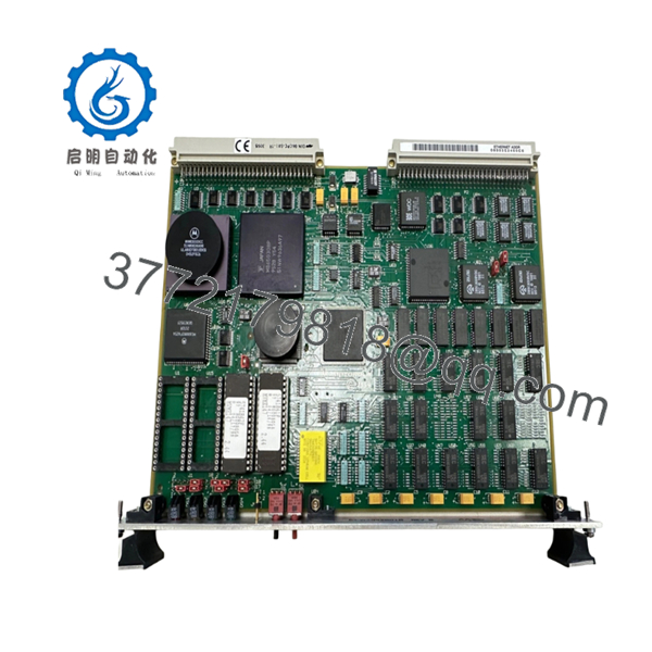
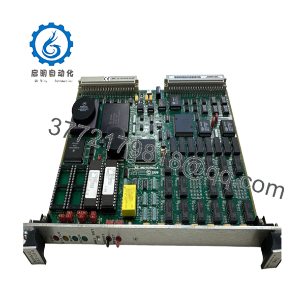
| Model | MVME147-014 |
| Processor | Motorola MC68030 |
| CPU Speed | 25 MHz |
| Floating Point Unit | MC68882 @ 25 MHz |
| Main Memory | 32 MB DRAM |
| Non-Volatile Memory | 4 KB Battery-Backed SRAM |
| Ethernet Controller | AMD AM7990 LANCE |
| Ethernet Interface | 10 Mbps Ethernet (AUI) |
| SCSI Interface | Onboard SCSI Controller |
| Serial Ports | 4 × RS-232 Asynchronous Ports |
| Parallel Port | 1 × Centronics-Compatible Port |
| Bus Interface | VMEbus A32/D32 Master/Slave |
| Watchdog Timer | Integrated |
| Real-Time Clock | Battery-Backed RTC |
| Form Factor | 6U Single-Slot VMEbus SBC |
| Operating Temperature | 0 °C to +55 °C |
| Storage Temperature | -40 °C to +85 °C |
The MVME147-014 represents the highest-memory configuration of the standard 25 MHz MVME147 family, combining a 32 MB DRAM configuration with onboard Ethernet and SCSI interfaces.
4. Product Introduction
The Motorola MVME147-014 is a 6U VMEbus single-board computer built around the Motorola MC68030 processor running at 25 MHz. The board integrates Ethernet, SCSI, serial communications, parallel I/O, real-time clock functionality, and watchdog supervision on a single VME module.
In field deployments during the 1990s, the MVME147-014 was widely used in process control systems, military electronics, telecommunications infrastructure, and scientific instrumentation. Engineers often selected the -014 variant because its 32 MB memory configuration was the largest available in the standard 25 MHz MVME147 product line.

- MVME147-014
- MVME147-014
5. Installation & Configuration Guide
Stage 1: Pre-Installation Preparation (10 Minutes)
⚠️ Safety First
- Notify operations personnel of planned downtime.
- Verify all controlled equipment is in a safe state.
- Perform lockout/tagout procedures.
- Remove power from the VME chassis.
- Wait at least 5 minutes for power supply discharge.
Tools Required
- ESD wrist strap
- PH1 screwdriver
- Fluke 115 multimeter
- Wire markers
- Smartphone camera
- Terminal emulator laptop
Data Backup
- Backup operating system files from attached SCSI storage.
- Record boot parameters.
- Document Ethernet settings.
- Photograph all rear-transition module connections.
- Record NVRAM and firmware settings.
Stage 2: Removing the Old Module (5 Minutes)
- Disconnect external Ethernet and serial interfaces.
- Label all attached cables.
- Release VME ejector handles.
- Pull the board straight from the backplane.
- Place the board on an ESD-safe surface.
⚠️ Note
Keep the original board available until the replacement has completed full system validation.
Inspection
- Inspect VME connectors for bent pins.
- Verify backplane integrity.
- Check transition-board connectors.
- Remove dust accumulation.
Stage 3: Installing the New Module (10 Minutes)
Critical Steps
- Attach ESD protection before handling the board.
- Verify the exact model is MVME147-014.
- Duplicate all jumper settings from the original board.
- Install the board into the card guides.
- Fully seat the board into the VME connector.
- Lock ejector handles.
- Reconnect all communication cables.
Configuration Clone (Crucial)
This is the most common rookie mistake, but it happens constantly.
Before removing the old board, photograph every jumper and switch. Many MVME147 systems rely on hardware-level configuration for boot source selection, VME arbitration, and system-controller settings.
Self-Checklist
- Part number verified
- Jumpers duplicated
- Backplane seated correctly
- Ethernet connected
- SCSI connected
- ESD procedures followed
Stage 4: Power-On & Testing (10 Minutes)
Pre-Power Check
- Verify +5 V power rail integrity.
- Check for shorts to chassis ground.
- Inspect SCSI termination.
Power-On Steps
- Energize the VME chassis.
- Observe RUN and FAIL indicators.
- Connect through the console port.
- Verify 147Bug monitor startup.
- Confirm memory count reports 32 MB.
- Test Ethernet communication.
- Verify SCSI device detection.
- Start the operating system.
⚠️ Troubleshooting Note
If the FAIL LED remains active after startup, suspect firmware issues, damaged NVRAM, or incorrect jumper configuration. If Ethernet communication fails, verify the AUI transceiver and external media converter before replacing the board.
6. Frequently Asked Questions (FAQ)
Q1. Can I hot-swap the MVME147-014?
No.
The MVME147 platform predates modern hot-swap VME implementations. Removing the board under power can damage both the SBC and the VME backplane.
Q2. Is the MVME147-014 obsolete?
Yes.
The MVME147 family has been out of OEM production for many years. Available inventory is typically sourced from surplus stock, asset recovery programs, or tested refurbished equipment.
Q3. What operating systems can run on the MVME147-014?
Common deployments included:
- VxWorks
- pSOS
- LynxOS
- UNIX variants
- Motorola 147Bug Monitor
Many legacy industrial systems continue to operate these platforms decades after installation.
Q4. What makes the -014 version different?
The MVME147-014 includes:
- 25 MHz MC68030 CPU
- 32 MB DRAM
- Ethernet
- SCSI
Within the 25 MHz MVME147 product family, the -014 configuration provides the highest standard memory capacity.
Q5. Will I lose my application software when replacing the board?
Usually not.
Application software normally resides on SCSI storage devices. However, configuration settings stored in battery-backed NVRAM should be documented before replacement.
Q6. What is the most common field failure?
Battery-backed NVRAM issues.
I’ve seen systems fail to boot after years of reliable operation because the onboard battery could no longer retain configuration data. Engineers often suspect the CPU first when the actual problem is NVRAM retention.
Q7. Why is pricing still high for a board this old?
Because downtime is expensive.
A replacement MVME147-014 can restore a production line, test stand, radar system, or utility control platform without requiring a complete redesign. For many facilities, sourcing a spare board is far less expensive than migrating the entire control architecture.
Technical Pitfall & Survival Guide
❗ Firmware Revision Mismatch
I’ve seen a replacement MVME147 installed successfully, only for the operating system to hang during startup.
The replacement hardware carried a different monitor revision than the original system expected.
Avoidance: Document the 147Bug revision before removal and request matching firmware whenever possible.
❗ DIP Switch / Jumper Misconfiguration
This remains one of the most common commissioning failures.
One incorrect jumper can change:
- System controller assignment
- Boot source selection
- VME arbitration behavior
Avoidance: Take clear photographs before removing the old board.
❗ SCSI Termination Errors
Many engineers immediately suspect the CPU board when storage devices disappear.
In reality, improper SCSI termination is often the culprit.
Avoidance: Verify termination resistors and cable orientation before troubleshooting software.
❗ Power Draw Specifications
The MVME147 itself is not particularly demanding, but fully populated VME racks often operate near power-supply limits.
Avoidance: Calculate total chassis consumption and maintain at least a 20% reserve capacity.
❗ Electrostatic Discharge (ESD)
I once watched an engineer pull an MVME147 from a running maintenance bench without an ESD strap during winter. The board passed diagnostics initially, then developed intermittent Ethernet failures that took days to isolate.
Avoidance: Always use a grounded wrist strap and ESD-safe work surface.
Keep these checks in mind and you’ll save yourself 90% of typical rework time.


