
 WhatsApp: +86 16626708626
 Email:
  Phone: +86 16626708626
Description
3. Key Technical Specifications
| Parameter | Value |
|---|---|
| Model | MVME1600-001 |
| Board Type | VMEbus Base Board |
| Form Factor | Double-Height VME Module |
| Processor Support | PM603 or PM604 Processor/Memory Modules |
| CPU Architecture | PowerPC 603 / PowerPC 604 |
| Expansion Support | PMC Mezzanine Card Support |
| DRAM Expansion | RAM104 Expansion Compatible |
| Transition Module | MVME760 |
| VME Interface | ANSI/IEEE 1014 VMEbus |
| Input Voltage | +5 VDC ±5% |
| Current Consumption | 2 A Typical, 3 A Maximum |
| Auxiliary Power | +12 VDC, 100 mA Maximum |
| Operating Temperature | 0 °C to 55 °C |
| Storage Temperature | -40 °C to +85 °C |
| Relative Humidity | 5% to 90% Non-Condensing |
| Board Dimensions | 233 mm × 160 mm Base Board |
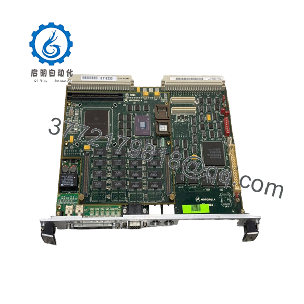
The MVME1600-001 serves as the base platform for MVME1603 and MVME1604 single-board computer systems. Processor, memory, and optional PMC modules are installed as mezzanine assemblies on the base board.
4. Product Introduction
The Motorola MVME1600-001 is a VMEbus single-board computer base board used in the MVME1603 and MVME1604 embedded computing platforms. It provides the VMEbus interface, I/O infrastructure, PMC expansion capability, and support for PM603 or PM604 PowerPC processor modules.
In industrial control, defense, telecommunications, and scientific computing systems, the MVME1600-001 became a common platform because engineers could upgrade CPU performance by replacing mezzanine processor modules rather than the entire board. The architecture also supports DRAM expansion and PMC add-on hardware for application-specific requirements.

- MVME1600-001
- MVME1600-001
5. Installation & Configuration Guide
Stage 1: Pre-Installation Preparation (10 Minutes)
⚠️ Safety First
- Notify operations personnel of scheduled downtime.
- Verify the controlled equipment is in a safe state.
- Apply lockout/tagout procedures.
- Remove power from the VME chassis.
- Wait at least 5 minutes for power supplies to discharge.
Tools Required
- ESD wrist strap
- PH1 screwdriver
- Fluke 115 multimeter
- Label markers
- Smartphone camera
- Flashlight
Data Backup
- Export operating system and application configurations.
- Record VME slot assignments.
- Photograph all rear transition module connections.
- Document PMC and DRAM mezzanine configurations.
- Record firmware and boot monitor versions.
Stage 2: Removing the Old Module (5 Minutes)
- Disconnect network, serial, and transition-module cables.
- Label every connection.
- Release ejector handles.
- Pull the board straight out of the VME backplane.
- Place the board on an ESD-safe surface.
⚠️ Note
Do not discard the original board until the replacement passes full operational testing.
Inspection
- Check VME connectors for bent pins.
- Inspect PMC connectors.
- Verify DRAM mezzanine sockets are undamaged.
- Remove dust contamination.
Stage 3: Installing the New Module (10 Minutes)
Critical Steps
- Wear an ESD strap before touching the board.
- Verify the exact part number is MVME1600-001.
- Transfer processor, memory, and PMC modules if required.
- Duplicate all jumper settings exactly.
- Install the board into the VME card guides.
- Seat the board firmly into the backplane.
- Lock ejector handles.
- Reconnect all cables.
Configuration Clone (Crucial)
Many MVME1600 systems have custom field configurations.
Take photos before removal. I have seen maintenance teams spend an entire shift troubleshooting a board that was installed with one incorrect jumper position.
Self-Checklist
- Board fully seated
- Processor module installed
- DRAM module installed
- PMC module installed
- Cabling verified
- Jumper settings copied
Stage 4: Power-On & Testing (10 Minutes)
Pre-Power Check
- Verify +5 V rail integrity.
- Measure chassis supply voltages.
- Check for shorts between power and ground.
Startup Procedure
- Power the VME chassis.
- Observe front-panel LEDs.
- Access the boot monitor.
- Verify processor recognition.
- Verify installed memory.
- Test Ethernet connectivity.
- Verify SCSI functionality if installed.
- Confirm VMEbus communication.
⚠️ Troubleshooting Note
- Solid fault LEDs frequently indicate processor mezzanine issues.
- Boot failures often trace back to improperly seated PM603 or PM604 modules.
- Communication failures commonly result from transition module mismatches.
6. Frequently Asked Questions (FAQ)
Q1. Can I hot-swap the MVME1600-001?
No.
The MVME1600 platform was not designed for hot insertion. Removing or inserting the board under power can damage both the module and the VME backplane.
Q2. Is the MVME1600-001 obsolete?
Yes.
Motorola discontinued the MVME1600 family many years ago. Current inventory is typically surplus stock, refurbished units, or recovered industrial spare parts.
Q3. Does the MVME1600-001 include a processor?
Not by itself.
The MVME1600-001 is a base board. It requires a PM603 or PM604 processor/memory mezzanine module to function as a complete single-board computer.
Q4. Which processors are compatible?
Supported processor modules include:
- PM603 Series (PowerPC 603)
- PM604 Series (PowerPC 604)
Compatibility depends on board revision and firmware level. Verify existing hardware before ordering.
Q5. What is the replacement if this board is unavailable?
The safest replacement is another MVME1600-001 of the same revision.
Although MVME1600-011 boards appear similar, their I/O implementation differs. Do not assume interchangeability without reviewing system documentation.
Q6. Will my software remain intact during replacement?
Usually yes.
Application software typically resides on storage devices or memory modules associated with the processor mezzanine. However, always perform backups before maintenance work.
Q7. Why do surplus units cost less than OEM pricing?
Most available inventory originates from:
- Decommissioned industrial systems
- Project surplus stock
- Asset recovery programs
- Legacy spare-parts inventories
Request photographs, serial numbers, and test documentation before purchasing.
Technical Pitfall & Survival Guide
❗ Firmware Revision Mismatch
I’ve seen a PowerPC module upgraded from one firmware release to another and suddenly the system stopped booting VxWorks correctly.
Avoidance: Record firmware versions before removal. Request matching revisions when sourcing replacements.
❗ DIP Switch / Jumper Misconfiguration
This remains one of the most common causes of startup failures.
Avoidance: Photograph every switch and jumper before touching the hardware.
❗ Terminal Block / Transition Module Incompatibility
MVME1600-001 typically uses the MVME760 transition module.
Installing the wrong transition hardware can produce communication failures that look like CPU faults.
Avoidance: Verify the rear transition module part number before commissioning.
❗ Power Consumption Planning
The base board itself requires approximately 2 A typical on the +5 V rail before processor and expansion modules are considered. Additional PMC and memory hardware increase power requirements.
Avoidance: Calculate total chassis power demand and maintain at least a 20% reserve margin.
❗ Electrostatic Discharge (ESD)
I once watched a technician replace a PowerPC mezzanine without grounding himself during winter maintenance. The board passed initial power-up and failed permanently during commissioning.
Avoidance: Use a grounded wrist strap and ESD mat whenever handling MVME1600 hardware.
Keep these checks in mind and you’ll save yourself 90% of typical rework time.


