
 WhatsApp: +86 16626708626
 Email:
  Phone: +86 16626708626
Description
Key Technical Specifications
| Parameter | Value |
|---|---|
| CPU | MC68LC040 microprocessor, 25 MHz clock speed |
| Memory (per -213 ordering code) | 4 MB DRAM (non-ECC) |
| SRAM | 128 KB with battery backup |
| NVRAM / RTC | 8K x 8 NVRAM with time-of-day clock, battery backed |
| Onboard Interfaces (per -213 config) | SCSI bus interface with 32-bit local bus burst DMA, and Ethernet transceiver interface with 32-bit local bus DMA |
| Serial Ports | Four serial communication ports, configured as EIA-232-D DTE |
| IndustryPack Slots | Two IndustryPack mezzanine ports |
| Timers | Six 32-bit timers (four without VMEbus) plus a watchdog timer |
| EPROM/Flash Sockets | Four 32-pin JEDEC sockets (models MVME162-2xx/3xx configuration) |
| VMEbus Interface | 4-level requester, 7-level interrupter, 7-level interrupt handler |
| Form Factor | Standard 6U VMEbus board |
⚠️ Confirm the exact revision (base MVME162-213 vs. the “-213A” hardware revision) against the seller’s label and the Motorola/Motorola Computer Group datasheet — Motorola revised chip sets (Petra ASIC vs. earlier MC2/IP2 chips) across the product’s life, and revision affects firmware compatibility.
Product Introduction
The MVME162-213 is a 6U VMEbus embedded controller from Motorola Computer Group, built around the MC68LC040 microprocessor running at 25 MHz. The “-213” designation in Motorola’s ordering scheme specifies the 4 MB DRAM, no-ECC configuration with both onboard SCSI and Ethernet interfaces populated — distinguishing it from other MVME162 variants that ship with only one interface, ECC memory, or no network/storage interface at all.
It was one of the highest-volume VMEbus boards ever sold, which is exactly why it still shows up in legacy telecom, defense, and industrial control systems today. The board’s four serial ports, dual IndustryPack mezzanine slots, and battery-backed SRAM/NVRAM made it a flexible OEM platform in its day — the trade-off now is that you’re sourcing 1990s-era silicon exclusively through the surplus market, so functional testing before shipment matters more here than on nearly any DCS/PLC part in this catalog.
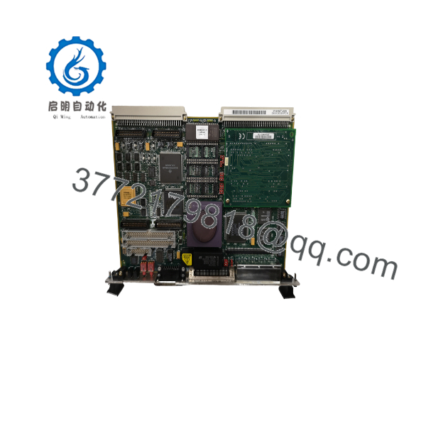
MVME162-213
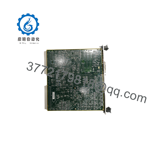
MVME162-213
Installation & Configuration Guide
Stage 1: Pre-Installation Preparation (~10 min)
⚠️ Safety First: Notify operations of the downtime window, confirm the VME chassis backplane is de-energized, and lock out/tag out the chassis power supply before removing any board.
Tools Required: ESD wrist strap, PH1/PH2 screwdriver for card-cage retainers, digital multimeter, wire labels for any front-panel cabling, smartphone for reference photos.
Data Backup: Record the 162-Bug environment settings (MPU clock speed, boot parameters, GCSR group address, system controller designation) from the outgoing board’s configuration menu before removal — these are board-specific and not stored on removable media on this platform.
Stage 2: Removing the Old Module (~5 min)
- Remove the front panel bezel if present.
- Label and disconnect any front-panel Ethernet, SCSI, or serial cabling.
- Release the top and bottom card-cage injector/ejector handles.
- Slide the board straight out along its guide rails to avoid stressing the VME P1/P2 backplane connectors.
- Inspect the P1/P2 connector pins on the backplane for bends or corrosion.
⚠️ Keep the old board available until the replacement is confirmed booting — its documented 162-Bug environment settings are your only configuration reference on this platform.
Stage 3: Installing the New Module (~15 min)
- ESD prep. Confirm the board is genuinely an MVME162-213 (or 213A) — other suffixes in the same family carry different memory sizes, ECC support, or missing SCSI/Ethernet interfaces and are not functionally interchangeable.
- Configuration clone (critical): Re-enter the documented 162-Bug environment settings, including system-controller status and GCSR group address, so the board takes its correct place on the VMEbus.
- Slide the board into the guide rails and engage the injector/ejector handles fully — confirm even seating against the P1/P2 backplane connectors.
- Reattach front-panel Ethernet, SCSI, and serial cabling per your labels.
Self-Checklist: [ ] 162-Bug environment settings restored [ ] System controller jumper/setting correct [ ] Cabling reattached per labels [ ] Injector/ejector handles locked
Stage 4: Power-On & Testing (~15 min)
Pre-Power Check: Multimeter check on the backplane supply rails for shorts before re-energizing the chassis.
- Power up the chassis and watch for the board to boot to the 162-Bug debug monitor prompt.
- Verify the environment settings match your documentation.
- Confirm Ethernet link status and, if applicable, SCSI device enumeration from the bug monitor or boot loader.
- Load and boot the application image (VxWorks, RTEMS, or other OS image used in the original system).
- Dry-run test network and SCSI I/O before returning the system to production.
⚠️ Troubleshooting Note: If the board doesn’t reach the 162-Bug prompt, suspect a mismatched system-controller jumper setting or GCSR address conflict with another board in the same chassis before assuming board failure — this is a common misconfiguration on multi-board VME crates.
Frequently Asked Questions (FAQ)
Can the MVME162-213 be hot-swapped under power?
No. Standard VMEbus boards are not hot-swap rated on this platform — pull chassis power and confirm de-energized backplane rails before removing or inserting the board.
Is the -213 obsolete, and is “new” stock genuinely new?
Yes, it’s obsolete — Motorola Computer Group’s VME line has been discontinued for a long time, and this board has been out of new production for decades. Any stock represents pulled surplus, tested refurbished units, or occasionally unused old-stock inventory. Be explicit with buyers about which of those three applies to the specific unit you’re quoting.
What’s the direct replacement if the -213 is out of stock?
There isn’t a drop-in modern replacement — Motorola/Motorola Computer Group’s VME product line has no active successor family carrying forward the same 162-Bug firmware and backplane environment settings. Buyers typically source a/213A unit specifically, or plan a broader system redesign around a currently-supported VME or embedded platform if long-term supportability is the concern.
Will I lose my configuration when I swap the board?
Yes, unless you document it first. Unlike some PLC modules with removable configuration media, the stores its 162-Bug environment settings (boot parameters, memory map, GCSR address) directly on the board’s battery-backed NVRAM. Record those settings from the old board before removal, or you’re reconstructing them from scratch on the replacement.
How do I know if a has SCSI and Ethernet, or just one?
Check the exact ordering suffix. Per Motorola’s original ordering table, the -213/-213A code specifically denotes the 25 MHz MC68LC040, 4 MB DRAM configuration with both SCSI and Ethernet interfaces populated — other suffixes in the -2xx/-3xx range carry only one interface, no interface, or different memory sizes and are not the same functional board even though they share the family name.
Why is your price lower than what I see for “new” listings elsewhere?
On a board this old, “lower price” almost always tracks directly to condition and testing depth rather than a lesser product — a pulled, untested board and a load-tested, NVRAM-battery-verified board are not the same offering even at the same part number. State plainly whether the unit was functionally tested under load, what the NVRAM battery status is, and whether the 162-Bug firmware revision was verified before it shipped.



