
 WhatsApp: +86 16626708626
 Email:
  Phone: +86 16626708626
Description
3. Key Technical Specifications
| Parameter | Value |
|---|---|
| Manufacturer | Motorola Computer Group |
| Model | MVME162-511A |
| Product Type | VMEbus Embedded Controller |
| Processor | Motorola MC68040 with Integrated FPU |
| CPU Speed | 32 MHz |
| Form Factor | Double-Height 6U VME Module |
| DRAM | 4 MB Parity-Protected DRAM |
| SRAM | 512 KB Battery-Backed SRAM |
| Flash Memory | 1 MB Onboard Flash |
| NVRAM | 8 KB with Battery Backup |
| IndustryPack Support | 4 IP Ports |
| Serial Ports | 2 Serial Communication Ports |
| Ethernet | Optional DMA Ethernet Interface |
| SCSI | Optional DMA SCSI Interface |
| VMEbus Support | A16, A24, A32 Addressing |
| Data Width | D8, D16, D32 |
| Watchdog Timer | Supported |
| Real-Time Clock | Battery-Backed TOD Clock |
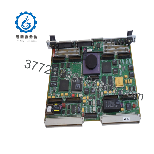
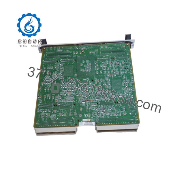
The MVME162-511A is a Motorola MC68040-based VMEbus embedded controller featuring 4 MB DRAM, 512 KB battery-backed SRAM, 1 MB Flash memory, and four IndustryPack expansion ports. The board serves as a VMEbus master/slave controller for industrial automation, telecommunications, aerospace, and embedded computing systems.
4. Product Introduction
The Motorola MVME162-511A is a high-performance VMEbus single-board computer built around a 32 MHz MC68040 processor with integrated floating-point support. The board combines CPU processing, memory management, serial communications, IndustryPack expansion capability, watchdog functions, and VMEbus control on a single 6U module.
In field deployments of semiconductor equipment, process control systems, military electronics, and telecommunications infrastructure, the MVME162 platform became popular because it provided Ethernet, SCSI, IndustryPack I/O expansion, and deterministic real-time operation without requiring additional processor hardware. Many facilities continue supporting these systems because software migration costs often exceed the cost of maintaining spare processor inventory.

- MVME162-511A
- MVME162-511A
5. Installation & Configuration Guide
Stage 1: Pre-Installation Preparation (10 Minutes)
⚠️ Safety First
- Notify operations personnel of scheduled downtime.
- Place the process into a verified safe state.
- Apply lockout/tagout procedures.
- Remove VME chassis power.
- Wait a minimum of 5 minutes for power supply discharge.
Tools Required
- ESD wrist strap
- PH1 screwdriver
- Fluke 115 multimeter
- Wire markers
- Smartphone for documentation
- Flashlight
Data Backup
- Export application software and operating system files.
- Record network configuration settings.
- Document IndustryPack module locations.
- Photograph all jumper settings.
- Record serial communication parameters.
- Document MVME162BUG firmware revision.
Stage 2: Removing the Old Module (5 Minutes)
- Remove chassis access covers.
- Label all connected cables.
- Disconnect transition module connections.
- Remove IndustryPack modules if required.
- Release board retention hardware.
- Operate ejector handles evenly.
⚠️ Do not pull one side before the other. Uneven force can bend VME connectors and create intermittent faults.
- Remove the board straight out of the chassis.
- Inspect:
- P1 connector
- P2 connector
- Backplane contacts
- Dust contamination
- Bent pins
- Corrosion
⚠️ Keep the original board until the replacement completes commissioning successfully.
Stage 3: Installing the New Module (10 Minutes)
- Attach grounded ESD protection.
- Verify the exact model number:
MVME162-511A
Configuration Clone (Crucial)
- Replicate all jumper positions exactly.
- Verify IndustryPack module placement.
- Verify serial interface module configuration.
- Verify SCSI and Ethernet settings.
- Verify system controller configuration.
❗ This is the most common rookie mistake, but it happens constantly. Take a picture before you pull it. I can’t stress this enough.
- Insert the board evenly into the VME slot.
- Fully engage ejector handles.
- Secure retention hardware.
- Reinstall IndustryPack modules.
- Reconnect all cables.
Self-Checklist
- Model verified
- Jumpers duplicated
- IP modules installed
- Board fully seated
- Wiring secured
Stage 4: Power-On & Testing (15 Minutes)
Pre-Power Check
- Verify no shorts on the +5 V rail.
- Confirm connector seating.
- Verify transition module installation.
Power-On Procedure
- Energize the VME chassis only.
- Observe startup indicators.
- Verify MVME162BUG monitor startup.
- Verify memory count.
- Verify serial communications.
- Verify Ethernet operation if installed.
- Verify SCSI device detection if installed.
- Perform dry-run I/O testing.
Troubleshooting Note
⚠️ If the board fails to boot, check firmware revision and memory configuration before replacing hardware.
⚠️ If Ethernet communication fails, verify the transceiver configuration and cabling.
⚠️ If IndustryPack modules are not detected, inspect carrier configuration and DMA settings.
Common Replacement Risks from the Field
❗ Firmware Revision Mismatch
I’ve seen maintenance crews install a replacement MVME162 during a shutdown only to spend two days troubleshooting communication errors.
The hardware was fine.
The replacement carried a different MVME162BUG firmware revision.
Avoidance: Record the existing firmware version before removal and request matching revisions when ordering spare inventory.
❗ DIP Switch and Jumper Misconfiguration
The MVME162 contains multiple hardware configuration jumpers controlling memory, VMEbus operation, and peripheral settings.
Avoidance: Photograph every jumper before removal and duplicate settings exactly.
❗ IndustryPack Module Issues
Many installations use custom IndustryPack I/O modules.
A replacement CPU board may boot successfully but still fail to communicate with installed IP modules.
Avoidance: Document all IndustryPack configurations before shutdown.
❗ Power Draw Calculations
The MVME162 itself is modest in power consumption, but fully populated IndustryPack systems can significantly increase chassis load.
Avoidance: Calculate total rack consumption and maintain a minimum 20% power reserve.
❗ Electrostatic Discharge (ESD)
I once watched a technician swap a 68040 board during a winter maintenance outage without grounding himself.
The board booted. Ethernet never worked again.
That’s an expensive lesson.
Avoidance: Always use a grounded wrist strap and ESD-safe work surface.
Keep these checks in mind and you’ll save yourself 90% of typical rework time.
6. Frequently Asked Questions (FAQ)
Q1. Can I hot-swap the MVME162-511A?
No.
The MVME162 family was not designed for hot-swapping. Removing the board under power can interrupt VMEbus transactions and potentially damage the controller or backplane.
Q2. What processor does the MVME162-511A use?
The MVME162-511A uses a Motorola MC68040 processor operating at 32 MHz and includes an integrated floating-point unit (FPU).
Q3. How much memory does the MVME162-511A include?
The MVME162-511A configuration includes:
- 4 MB DRAM
- 512 KB battery-backed SRAM
- 1 MB Flash memory
- 8 KB battery-backed NVRAM
These specifications are associated with the 511A model variant.
Q4. What are the four IndustryPack ports used for?
IndustryPack (IP) ports allow expansion with specialized I/O modules such as:
- Analog input/output
- Digital I/O
- Serial communications
- Motion control
- Data acquisition
This architecture made the MVME162 highly flexible for OEM applications.
Q5. Is the MVME162-511A obsolete?
Yes.
Motorola discontinued the MVME162 platform many years ago. Current availability is generally limited to surplus inventory, tested used equipment, and professionally refurbished units.
Q6. Will I lose my application software during replacement?
Not necessarily.
Most applications reside in Flash memory, EPROM devices, external storage, or network boot environments. However, always perform a complete backup before maintenance activities.


