WhatsApp: +86 16626708626
 Email:
 Phone: +86 16626708626
Description
3. Key Technical Specifications
- Processor: MC68040, 32 MHz, 32-bit, with integrated FPU, MMU, and 8 KB cache — the top-performing CPU option in the MVME162 line
- DRAM: 4 MB onboard parity-protected DRAM
- SRAM: 512 KB battery-backed SRAM
- Flash Memory: Onboard Flash with 162Bug debug monitor installed
- NVRAM / Clock: Battery-backed TOD clock and configuration NVRAM
- VMEbus Interface: Local bus to VMEbus / VMEbus to local bus, A16/A24/A32, D8/D16/D32, master/slave with system controller function
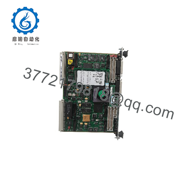
- Serial Ports: 2 × ports — EIA-232-D and EIA-232-D/EIA-530
- Ethernet: LAN transceiver interface with DMA (10BASE-T)
- SCSI: SCSI bus interface with DMA (NCR 53C710, async 5 MB/s, sync 10 MB/s)
- IndustryPack: 4 IP mezzanine slots (board occupies a single VME slot)
- Timers: 6 tick timers with watchdog timer(s)
- Power Requirements: +5 V DC ±5% (verify against your chassis budget with IP modules installed)
- Operating Temperature: 0 to +55 °C (typical spec; confirm against the MVME162 datasheet for your revision)
- Format: Double-high 6U VME card (233 mm × 160 mm), single slot
4. Product Introduction
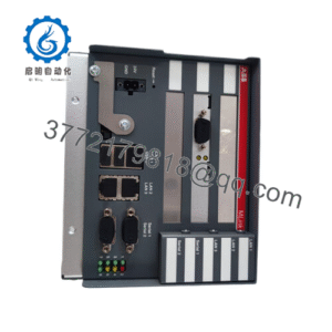
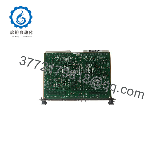
The Motorola MVME162-513A is a double-high VMEbus embedded controller built on the 32 MHz MC68040 — the fastest CPU tier in the MVME162LX family, with a hardware FPU, MMU, and 8 KB of internal cache. The -513A configuration pairs it with 4 MB of parity-protected DRAM, 512 KB of battery-backed SRAM, and both SCSI and Ethernet interfaces onboard, plus four IndustryPack mezzanine slots for analog, digital, or serial I/O expansion without using another VME slot.
System owners buy this exact variant because it’s what their platform was qualified on — industrial motion control, semiconductor tools, and test systems tuned around the 32 MHz 68040’s deterministic timing. A -513A is not interchangeable with the 25 MHz -2xx/-4xx variants without re-validating your timing behavior. Match the full part number on your installed board’s silkscreen before ordering, and verify against the MVME162LX datasheet.
5. Troubleshooting Quick Reference
| Symptom | Possible Cause | Relevance to this Part | Quick Check Method | Recommendation |
|---|---|---|---|---|
| FAIL LED lit at power-up | Local memory/Flash test failure or VMEbus address conflict | ✅ High | Note the yellow RUN LED pattern; break into 162Bug and run the full DRAM/Flash test | Check memory map conflicts with adjacent boards; if tests fail repeatedly on our board, we replace it — send us the 162Bug console output |
| Application runs but timing is off | Replaced a -2xx/-4xx (25 MHz) board with this 32 MHz unit (or vice versa) | ⚠️ Medium | Confirm the clock rate in 162Bug (CPUTYPE / board info command) against system documentation |
The bus runs 32 MHz here — re-qualify timing-critical loops before returning to production |
| Ethernet dead | Transceiver config, IP address setup, or patch cabling | ⚠️ Medium | Verify station address via 162Bug NIOT; check the 10BASE-T link light at the hub |
LAN controller chip failure is rare; check cable path first |
| SCSI devices not detected | SCSI ID conflict or bus termination | ⚠️ Medium | Confirm unique IDs; verify termination at both ends of the SCSI chain | Termination causes most “dead SCSI” complaints |
| Serial port garbage or dead console | EIA-232-D/EIA-530 jumper configuration mismatch | ✅ High | Verify serial port jumpers/headers against the manual; loop-back test each port | The second port supports both 232 and 530 — check the header config before condemning the port |
| Intermittent resets under load | Marginal +5 V backplane rail with IP modules installed | ⚠️ Medium | Measure +5 V ±5% at P1 with a Fluke 115 under full load, all IP modules seated | Calculate total chassis draw with a 20% margin; IP modules add real current |
| RTC / SRAM loses data on power-down | Dead lithium backup battery | ✅ High (common, minor) | Measure battery voltage (>2.8 V typical); inspect the holder for corrosion | Replace the battery before it leaks — leakage destroys the PCB beyond economical repair |
A note from the bench: the 500 Series boards come back “no fault found” more often than they come back broken. The usual real culprits: serial port jumper config (that EIA-530-capable second port trips people up), SCSI termination, or a VMEbus memory map conflict introduced by a board someone else added to the rack. Swap the suspect board into a known-good slot — if the fault follows the card, then call us. Stuck? Email technical support with photos of the front panel LEDs, the 162Bug power-up text, and your chassis configuration. We’ll tell you straight.
MVME162-513A
MVME162-513A
6. Frequently Asked Questions
Q1: Is this board new, refurbished, or new surplus?
Stock is a mix of New Surplus (factory-original, never deployed, often in sealed Motorola packaging) and refurbished units. Every unit, regardless of tier, goes through the same sequence: inbound traceability and anti-counterfeit checks, power-up on a genuine VME chassis, full DRAM and Flash test via 162Bug, loop-back verification on both serial ports, Ethernet and SCSI interface checks, and a 24-hour burn-in run with thermal monitoring. Test photos, reports, and video available on request. If you require true New Surplus, state it at order time — sealed -513A units are increasingly rare.
Q2: Why does this obsolete board cost so much, and is it even available?
Motorola Computer Group discontinued the MVME162 line years ago — no factory support, no new production, full stop. Supply is surplus and refurbished stock only, and the 32 MHz 500 Series units are scarcer than the 25 MHz variants. That scarcity drives the price, not a spec sheet fantasy. If a -513A keeps a production line or a qualified system running, my honest recommendation: buy the spare now. Sourcing one mid-failure takes weeks.
Q3: Can I substitute a -213, -413A, or another MVME162 variant?
Physically yes, functionally not without checking. The -513A runs a 32 MHz MC68040 with FPU; the -213 runs a 25 MHz MC68LC040 with no FPU. If your application performs hardware floating point math, an LC040 board will crash with F-line exceptions. Timing is the second trap: code tuned for 32 MHz may misbehave on 25 MHz silicon (or vice versa) in real-time loops. DRAM size and I/O set must match too. Verify the full ordering matrix against the MVME162LX datasheet and your system documentation before substituting anything.
Q4: Will my program and configuration survive a board swap?
Your application lives in Flash, EPROMs, or off-board storage, so the program survives if firmware matches — but two gotchas exist. First, the 512 KB battery-backed SRAM and the TOD/NVRAM lose stored data if the battery dies during the swap; back up your 162Bug configuration (serial settings, memory map, network parameters) first. Second, anything in DRAM is volatile and gone at power-down regardless. Photograph the board, jumpers, IP module positions, and cabling before pulling the card. I’ve watched a tech spend hours undoing an undocumented IP module configuration — take the ten minutes up front.
Q5: Can I hot-swap this board?
No. The MVME162 has no hot-swap support; that capability arrived with VME64x, long after this board was designed. Pulling it live risks damaging backplane bus drivers, corrupting other boards’ VMEbus cycles, or killing the board itself. Kill chassis power, wait for discharge, wear a grounded ESD wrist strap, and handle the board by its edges. I saw a static discharge take out a $3,000 controller in a dry equipment room in January because the tech skipped the strap. Use the strap — the two seconds it takes is cheaper than the board.
Q6: What about the onboard battery?
Inspect it at install time. The lithium cell backs up the SRAM, TOD clock, and NVRAM, and a cell that has sat for decades is overdue. A leaking cell corrodes the PCB — the single most common killer of otherwise healthy MVME162 boards. Our units ship with battery voltage measured and documented; any board showing corrosion at inbound inspection is rejected, not resold. If calibration or configuration data lives in battery-backed memory, back it up before touching the board.
Q7: What warranty and lead time do you offer?
Tested units ship with a 1-year replacement warranty covering functional failure under normal use — not physical damage, hot-swap damage, or battery leakage after receipt. In-stock boards ship in 1–2 business days via DHL/FedEx worldwide; out-of-stock units typically source in 2–4 weeks. Confirm stock and lead time before scheduling your maintenance window — a realistic “3 weeks” today beats a broken promise on shutdown day.