
 WhatsApp: +86 16626708626
 Email:
 Phone: +86 16626708626
Description
Core Product Summary (Brand / Model / Key Attributes)
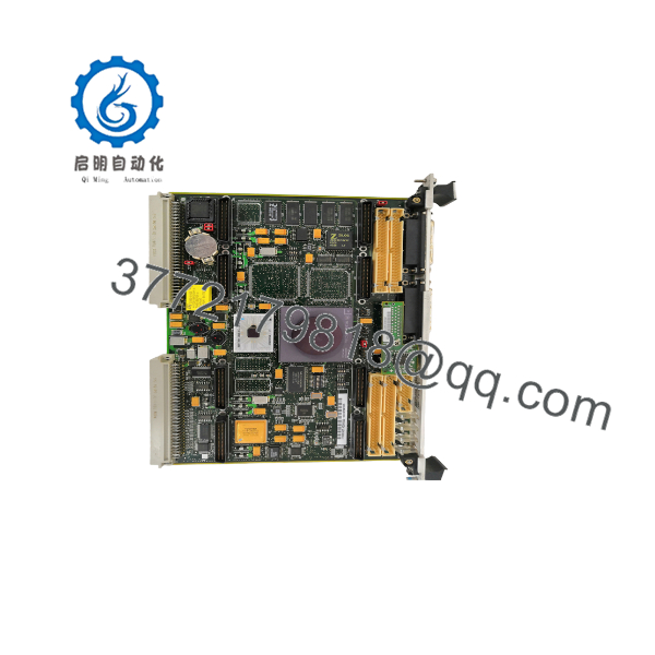
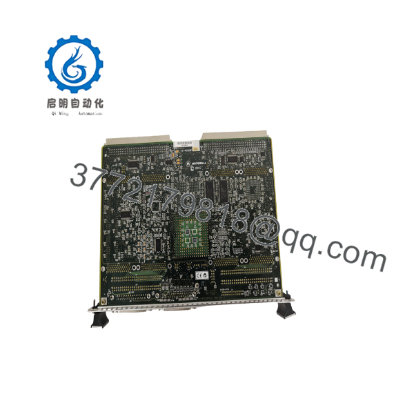
The Motorola MVME162PA-344SE (frequently cross-referenced in spare-parts systems as VME162PA344SE, assembly part numbers 01-W3528F 60A and 01-W3528F 60B) is a double-high (6U) VMEbus single-board computer and embedded controller from the Motorola Computer Group MVME162PA series. Engineered for real-time industrial control, data acquisition, and supervisory VME chassis tasks, it functions as an A32/D64 VMEbus master/slave processor with jumper-selectable Slot 1 System Controller capability.
Powered by a 32 MHz / 33 MHz Motorola MC68040 microprocessor with an integrated floating-point unit (FPU) and memory management unit (MMU), the MVME162PA-344SE provides 16 MB of onboard DRAM, 512 KB of battery-backed SRAM, and 1 MB of Flash memory. The -344SE hardware configuration integrates four 16-bit (or two 32-bit) DMA-capable IndustryPack mezzanine sites, two serial ports, an Ethernet interface, and a SCSI bus interface on a single VME slot.
Key Technical Specifications
| Parameter | Verified Specification |
|---|---|
| Manufacturer / Brand | Motorola Computer Group (later Emerson) |
| Model / Order Number | MVME162PA-344SE (Cross-Reference: VME162PA344SE; Assembly P/N: 01-W3528F 60A, 01-W3528F 60B) |
| Product Series | MVME162P / MVME162PA VME Embedded Controller Series |
| Product Type | Double-High (6U) VMEbus Single-Board Computer (SBC) / Embedded Controller |
| Microprocessor | Motorola MC68040 (MC68040RC33A, 32 MHz / 33 MHz class) with integrated MMU and Floating-Point Unit (FPU) |
| Main Memory | 16 MB onboard DRAM |
| Non-Volatile Memory | 512 KB battery-backed SRAM; 1 MB onboard Flash memory; 8K × 8 NVRAM with battery-backed time-of-day clock |
| VMEbus Interface | A32/D64 VMEbus master/slave interface via VMEchip2 ASIC with jumper-selectable System Controller |
| Mezzanine Expansion | 4 × 16-bit (or 2 × 32-bit) ANSI/VITA 4 IndustryPack (IP) slots with 1 DMA channel per port |
| Network & Storage Interfaces | Onboard Ethernet LAN interface and SCSI bus interface |
| Serial Interfaces | 2 × serial communication ports (Port 1/Console: EIA-232-D DCE; Port 2: configurable via Serial Interface Module, e.g., SIMM06 EIA-232-D DCE) |
| Timers & Watchdog | Six 32-bit programmable tick timers and one hardware watchdog timer |
| Front-Panel Controls & LEDs | RESET and ABORT switches; 8 status LEDs (FAIL, STAT, RUN, SCON, LAN, FUSE, SCSI, VME) |
| Form Factor | 6U double-high VMEbus module (P1 and P2 backplane connectors) |
Detailed Product Overview
The Motorola MVME162PA-344SE provides complete real-time computing, VMEbus arbitration, and local mezzanine I/O within a single 6U VMEbus card slot. Built around the Motorola MC68040 microprocessor, it pairs on-chip instruction and data caches with an integrated floating-point coprocessor to handle deterministic control algorithms, real-time operating systems, and multi-axis or process-control tasks.
Backplane transactions are governed by the VMEchip2 ASIC, which supports full A32/D64 master/slave transfers, burst cycles, and system controller arbitration. Through header J1, engineers can configure the card either as the dedicated Slot 1 VMEbus System Controller or as an auxiliary processor in multi-CPU VME chassis architectures.
The -344SE suffix specifies a high-integration board variant combining 16 MB of DRAM (3), four IndustryPack ports (4), two serial channels (4), a SCSI bus controller (S), and an Ethernet LAN controller (E). Rather than dedicating separate VME backplane slots to peripheral controllers or low-channel-count I/O, up to four single-wide (or two double-wide) IndustryPack mezzanine modules can mount directly onto the MVME162PA-344SE carrier with dedicated DMA support. Onboard Flash memory houses the 162Bug monitor/debugger or application boot code, while 512 KB of battery-backed SRAM preserves critical runtime states and real-time clock data across power cycles.
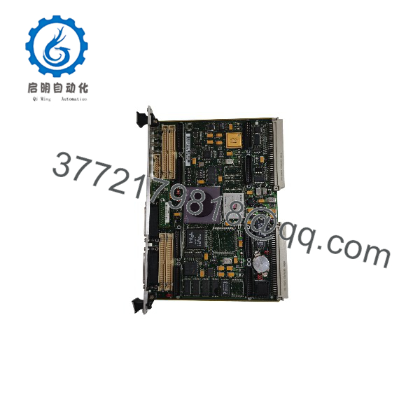
MVME162PA-344E
Engineering Selection Highlights
- Exact
-344SEbuild identification → Verifies 16 MB DRAM, four DMA-capable IndustryPack sites, two serial ports, SCSI interface, and Ethernet interface, preventing mismatches with lower-memory or non-SCSI/non-Ethernet MVME162 models. - High-density IndustryPack mezzanine support → Accepts up to four 16-bit or two 32-bit ANSI/VITA 4 IndustryPack modules directly on the carrier PCB, allowing existing field I/O mezzanines to move onto a replacement board.
- Configurable VMEbus System Controller (
J1) → Operates as the VMEbus Slot 1 System Controller when jumperJ1is installed, or as a standard VME master/slave card in non-Slot-1 chassis positions whenJ1is removed. - Interchangeable Serial Port B module (
J15) → Uses a plug-in Serial Interface Module (SIM), such asSIMM06for EIA-232-D DCE, allowing Port B electrical signaling to match existing transition panels and serial cabling. - Hardware jumper and switch parity (
J1–J24,S3–S6) → Requires duplicating all onboard header jumpers and DIP-switch settings from the original unit so memory sizing, IP bus clock frequency, and VMEbus arbitration align with installed firmware.
System Compatibility & Integration Requirements
| Item / Dependency | Verified Compatibility or Requirement | Practical Note |
|---|---|---|
| Chassis / Backplane | Standard 6U VMEbus Backplane (P1 and P2 connectors) | Install in Slot 1 only when jumper J1 is installed for System Controller operation; remove J1 when installing in other slots. |
| IndustryPack Mezzanines | ANSI/VITA 4 IndustryPack (IP) modules (up to 4 single-wide or 2 double-wide) | Transfer existing IP mezzanine cards and confirm IP bus clock (J14) and reset/DMA switch settings (S5) match the application. |
| Serial Port B Interface | Motorola Serial Interface Module (SIM), e.g., SIMM06 (EIA-232-D DCE) |
Verify which SIM card is mounted on header J15 and match external transition cabling (such as MVME712M/MVME712X). |
| Ethernet & SCSI Connections | Onboard LAN interface and SCSI bus with external transition/front cabling | Verify external transition module or front-panel cabling and ensure proper SCSI bus termination. |
| Firmware & Monitor Environment | 162Bug monitor/debugger in onboard Flash / EPROM | Record and transfer ENV and CNFG parameters from the original board so network boot or Flash autoboot settings match. |
Dimensions, Mounting & Connection Notes
- Form Factor & Installation: Standard 6U double-high, single-slot VMEbus eurocard; align top and bottom PCB edges in the VME chassis card guides, press firmly until both P1 and P2 backplane connectors seat completely, and secure the front-panel ejector latches and retaining screws.
- Thermal & Airflow Requirements: Requires continuous forced-air chassis cooling across the main PCB and populated IndustryPack mezzanine modules; verify chassis cooling fans and filters prior to operation.
- Jumper & DIP-Switch Configuration: Before inserting a replacement board, match all onboard jumpers and switches—including VME System Controller (
J1), IP Bus Clock (J14), Serial Port clocks (J16,J17), SRAM backup source (J22), Flash write protection (J24), and DRAM/IP configuration switches (S3–S6). - ESD & Battery Precautions: Handle strictly at grounded ESD workstations; do not set the bottom of the circuit board on conductive surfaces that could short the onboard lithium backup battery leads.
FAQ
What is the Motorola -344SE? The Motorola MVME162PA-344SE (also listed as VME162PA344SE) is a 6U double-high VMEbus single-board computer and embedded controller equipped with an MC68040 processor, 16 MB DRAM, four IndustryPack slots, two serial ports, SCSI, and Ethernet.
What does the “-344SE” suffix indicate? In Motorola MVME162PA nomenclature, 3 designates 16 MB of onboard DRAM, the first 4 designates four IndustryPack mezzanine ports, the second 4 designates two serial interfaces, S indicates the SCSI interface, and E indicates the Ethernet interface.
How is the MVME162PA-344SE configured as a VMEbus System Controller? Installing jumper J1 enables the VMEchip2 System Controller function for VME Slot 1; removing J1 disables the System Controller function so the board can operate in any non-Slot-1 chassis position.
What do the eight front-panel LEDs represent? The eight status indicators (FAIL, STAT, RUN, SCON, LAN, FUSE, SCSI, VME) display self-test fault status, CPU status, CPU execution activity, Slot 1 System Controller state (SCON), onboard fuse health (FUSE), and LAN, SCSI, and VMEbus activity.
What should be transferred from an existing MVME162PA-344SE during a field replacement? Before swapping boards, transfer any installed IndustryPack mezzanine modules and the Serial Interface Module (J15), duplicate all header jumpers and DIP-switch settings, and copy the 162Bug ENV and CNFG parameters.
Verification & Troubleshooting Notes
- Pre-Removal Configuration Audit: Power down the VME chassis under lockout/tagout and photograph or record all jumper positions (
J1–J24), DIP-switch settings (S3–S6), Serial Interface Module model (J15), and IndustryPack slot assignments (A–D) before removing the original board. - Startup LED Verification: Upon energizing the VME chassis, verify that the
FAILLED extinguishes after power-on self-test andRUNilluminates; ifFAILremains lit, connect a serial terminal to Serial Port 1/Console to read 162Bug self-test diagnostic codes. - Onboard Fuse & Power Rail Check: If the front-panel
FUSELED illuminates or peripheral interfaces (LAN, SCSI, or IndustryPack modules) fail to respond, inspect the onboard fuses protecting the peripheral power feeds and verify +5 VDC and ±12 VDC VME backplane voltages. - System Controller Conflict Check (
SCONLED): Confirm thatSCONis lit only on the single processor board occupying VME Slot 1; multiple active System Controllers on the same backplane will block VMEbus arbitration. - NVRAM & Clock Retention Check: If real-time clock settings or 162Bug
ENVboot variables are lost after power-down, verify the SRAM/TOD backup battery jumper (J22) and check the onboard lithium backup battery voltage.



