
 WhatsApp: +86 16626708626
 Email:
  Phone: +86 16626708626
Description
3. Key Technical Specifications
| Parameter | Value |
|---|---|
| Model | MVME167-32A |
| Processor | Motorola MC68040 |
| CPU Speed | 33 MHz |
| Floating Point Unit | Integrated MC68040 FPU |
| Memory Configuration | 32 MB DRAM |
| SRAM | 128 KB Battery-Backed SRAM |
| Non-Volatile Memory | MK48T08 RTC/NVRAM |
| Ethernet Controller | Intel i82596CA |
| Ethernet Interface | 10 Mbps Ethernet |
| SCSI Controller | NCR 53C710 |
| Serial Ports | 4 × Serial Channels (CD2401) |
| Parallel Port | PCC2 Integrated Parallel Interface |
| VME Interface | VMEchip2 A32/D32 Master/Slave |
| Bus Format | 6U Single-Slot VMEbus SBC |
| Status Indicators | FAIL, STAT, RUN, SCON, LAN, +12V, SCSI, VME |
| Onboard Firmware | EPROM-based 167Bug Monitor |
| Operating Environment | Industrial Embedded Applications |
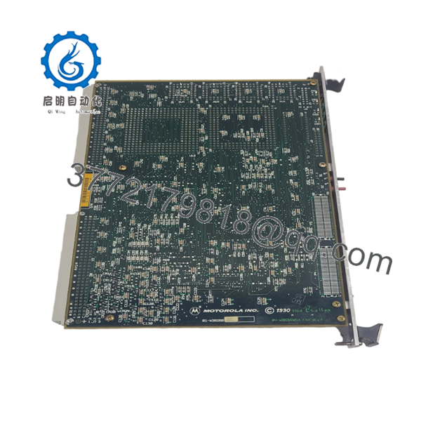
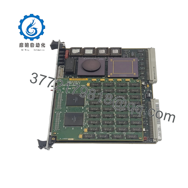
The MVME167-32A is a member of the Motorola MVME167 family built around the MC68040 processor with integrated MMU and floating-point hardware. The platform includes Ethernet, SCSI, serial communications, RTC/NVRAM, and VMEbus interfaces on a single 6U board.
4. Product Introduction
The Motorola MVME167-32A is a high-performance VMEbus single-board computer designed for embedded control, industrial automation, telecommunications, and defense applications. The board integrates a 33 MHz MC68040 processor, Ethernet networking, SCSI storage, serial communications, and VMEbus master/slave capability within a single-slot 6U form factor.
In field deployments, the MVME167-32A became one of Motorola’s most widely adopted VME CPU platforms because it combined processing, communications, and storage interfaces without requiring additional controller boards. Many legacy VME systems remain operational today using MVME167-family processors running VxWorks, OS-9, pSOS, and UNIX-derived operating systems.
- MVME167-32A

- MVME167-32A
5. Installation & Configuration Guide
Stage 1: Pre-Installation Preparation (10 Minutes)
⚠️ Safety First
- Notify operations personnel of planned downtime.
- Verify all controlled equipment is in a safe state.
- Apply lockout/tagout procedures.
- Remove power from the VME chassis.
- Wait at least 5 minutes for capacitor discharge.
Tools Required
- ESD wrist strap
- PH1 screwdriver
- Fluke 115 multimeter
- Wire labels
- Smartphone camera
- Terminal emulator laptop
Data Backup
- Backup operating system files.
- Record 167Bug boot parameters.
- Document Ethernet settings.
- Photograph rear-transition module wiring.
- Record VME arbitration and system-controller settings.
- Save application software and startup scripts.
Stage 2: Removing the Old Module (5 Minutes)
- Disconnect Ethernet, serial, and SCSI cables.
- Label all external connections.
- Release VME ejector handles.
- Pull the board straight out of the backplane.
- Place the module on an ESD-safe work surface.
⚠️ Note
Keep the original board available until the replacement completes operational testing and application validation.
Inspection
- Inspect VME connectors for bent pins.
- Verify card guides are undamaged.
- Check rear-transition modules.
- Remove dust and debris.
Stage 3: Installing the New Module (10 Minutes)
Critical Steps
- Connect ESD protection before handling the board.
- Verify the exact model number is MVME167-32A.
- Duplicate all jumper and switch settings from the original board.
- Insert the board into the VME guides.
- Fully seat the board into the backplane.
- Lock ejector handles.
- Reconnect Ethernet, serial, and SCSI interfaces.
Configuration Clone (Crucial)
This is the most common rookie mistake, but it happens constantly.
Take photographs before removal. I’ve seen engineers spend two days troubleshooting a replacement that was configured as the VME System Controller while another board was already performing that role.
Self-Checklist
- Part number verified
- Jumpers duplicated
- VME system-controller settings verified
- SCSI connections restored
- Ethernet connected
- ESD procedures followed
Stage 4: Power-On & Testing (10 Minutes)
Pre-Power Check
- Verify +5 V power rail integrity.
- Check for shorts between power and ground.
- Inspect SCSI termination.
- Verify VME backplane health.
Power-On Steps
- Energize the VME chassis.
- Observe status LEDs.
- Confirm RUN LED operation.
- Connect through the console port.
- Verify 167Bug monitor startup.
- Confirm memory recognition.
- Test Ethernet communication.
- Verify SCSI storage detection.
- Start the application software.
⚠️ Troubleshooting Note
If the FAIL LED remains illuminated, suspect firmware issues, NVRAM corruption, memory faults, or incorrect jumper configuration. If Ethernet fails, verify the transceiver and network configuration before replacing the board. The MVME167 uses dedicated LAN and SCSI status indicators that can significantly reduce troubleshooting time.
6. Frequently Asked Questions (FAQ)
Q1. Can I hot-swap the MVME167-32A?
No.
The MVME167 platform predates modern hot-swap VME implementations. Inserting or removing the board under power can damage the SBC and the backplane.
Q2. Is the MVME167-32A obsolete?
Yes.
The MVME167 family has been discontinued for many years. Current availability is limited to surplus inventory, tested refurbished units, and asset-recovery stock.
Q3. What operating systems typically run on the MVME167?
Common deployments include:
- VxWorks
- OS-9
- pSOS
- LynxOS
- NetBSD
- UNIX-based embedded platforms
Field users continue to operate MVME167 systems decades after deployment due to the stability of these operating environments.
Q4. What makes the MVME167-32A different from earlier MVME147 boards?
The MVME167 family upgrades the architecture from the MC68030 to the MC68040 processor and incorporates enhanced memory, Ethernet, SCSI, VMEchip2 bus management, and improved system integration.
Q5. Will replacing the CPU board erase my application?
Usually no.
Application software is normally stored on SCSI disks, flash storage, or external media. However, configuration information stored in NVRAM should always be documented before replacement.
Q6. What is the most common field failure?
Battery-backed NVRAM and aging memory components.
I’ve seen technicians replace perfectly good CPU boards when the actual problem was a failed RTC/NVRAM device that prevented the system from retaining boot parameters.
Q7. Why are MVME167 boards still expensive?
Because replacing a failed CPU board is often far cheaper than redesigning an entire VME control system.
Many military, transportation, utility, and industrial systems continue operating on VME hardware because the original software investment is substantial and the platforms remain reliable.
Technical Pitfall & Survival Guide
❗ Firmware Revision Mismatch
I’ve seen a replacement MVME167 boot successfully and then fail during operating-system startup because the installed 167Bug revision differed from the original hardware.
Avoidance: Record firmware revisions before removal and request matching versions whenever possible.
❗ DIP Switch / Jumper Misconfiguration
One incorrect jumper can change:
- System Controller assignment
- Boot source selection
- VME arbitration behavior
- Memory configuration
Avoidance: Photograph every jumper before touching the hardware.
❗ SCSI Termination Problems
Many engineers blame the CPU board when storage disappears.
In reality, SCSI termination errors are among the most common causes of boot failures on MVME167 systems.
Avoidance: Verify termination resistors, cable orientation, and device IDs before troubleshooting software.
❗ Power Draw Specifications
A fully populated VME rack can consume substantial power.
For example, adding CPU, memory, Ethernet, SCSI devices, and multiple I/O cards may push aging power supplies beyond safe operating margins.
Avoidance: Calculate chassis load and maintain at least a 20% reserve capacity.
❗ Electrostatic Discharge (ESD)
I once watched an engineer replace a MVME167 CPU board during a winter shutdown without grounding himself. The system booted successfully, then developed intermittent SCSI faults that took three days to isolate.
Avoidance: Use a grounded wrist strap and ESD-safe work surface every time.
SOP Quality Transparency
1. Inbound Inspection & Traceability
Every MVME167-32A should undergo:
- OEM label and part-number verification
- Serial-number traceability recording
- Anti-counterfeit inspection
- Visual examination for corrosion, rework marks, damaged traces, and UV discoloration
- Accessory verification and documentation review
2. Live Functional Testing
Testing should be performed on a genuine Motorola VME test chassis.
Procedure:
- Power-on self-test verification.
- 167Bug monitor startup confirmation.
- Ethernet communication test.
- Serial-port loopback testing.
- SCSI device detection test.
- VME backplane communication validation.
- Continuous operation under load for at least 24 hours.
A formal test report should be generated.
3. Electrical Parameter Testing
- Insulation resistance testing using a 500 V Megger (>10 MΩ).
- Ground continuity verification.
- Power rail measurements.
- Voltage stability checks under load.
4. Firmware & Configuration Verification
- Record firmware revision.
- Backup configuration settings.
- Photograph jumper settings.
- Verify memory configuration.
5. Final QC & Packaging
- Final inspector sign-off.
- Anti-static ESD packaging.
- Bubble-wrap protection.
- Heavy-duty corrugated carton.
- QC-passed label with test date.
Test photographs and operational videos should be available upon request. Verified fully functional under load testing is a more meaningful statement than any “100% guaranteed” marketing claim.


