
 WhatsApp: +86 16626708626
 Email:
  Phone: +86 16626708626
Description
3. Key Technical Specifications
| Parameter | Value |
|---|---|
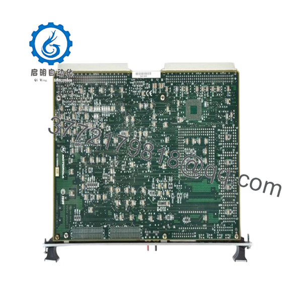
| Model | MVME167-33 |
| Processor | Motorola MC68040 |
| CPU Frequency | 33 MHz |
| Architecture | 32-bit CISC |
| Cache | 8 KB On-Chip Cache |
| Memory Options | 4 MB to 128 MB DRAM (Parity or ECC Depending on Variant) |
| SRAM | 128 KB |
| NVRAM/RTC | 8 KB with Battery Backup |
| VME Interface | Full 32-Bit Master/Slave VMEbus |
| DMA | High-Speed DMA, D64 Support |
| Ethernet | On-Board Ethernet Controller |
| SCSI | NCR53C710 SCSI Interface |
| Serial Ports | Four EIA-232-D Channels |
| Parallel Port | Centronics Compatible |
| Timers | Four 32-Bit Timers |
| Watchdog Timer | Integrated |
| Operating Temperature | 0 °C to +55 °C |
| Board Format | 6U VME Single-Board Computer |
| Product Status | Obsolete / Legacy Hardware |
The MVME167-33 is based on the MC68040 processor and integrates Ethernet, SCSI, serial communications, DMA capability, watchdog functions, and a full VMEbus interface on a single board. It was widely deployed in industrial automation, semiconductor manufacturing equipment, transportation systems, military electronics, and scientific instrumentation.
4. Product Introduction
The Motorola MVME167-33 is a high-performance VMEbus single-board computer built around the 33 MHz MC68040 processor. It combines CPU, memory management, floating-point processing, Ethernet networking, SCSI storage support, serial communications, and VMEbus control on a single 6U board.
Many OEM machine builders selected the MVME167-33 because it reduced rack complexity while maintaining compatibility with existing Motorola 68000-family software. In long-life industrial systems, replacing a failed MVME167-33 often avoids a complete software migration project that could require months of validation and commissioning.

- MVME167-33
- MVME167-33
5. Installation & Configuration Guide
Stage 1: Pre-Installation Preparation (10 Minutes)
⚠️ Safety First
- Notify operations personnel of planned downtime.
- Place all controlled equipment in a safe state.
- Apply Lock-Out/Tag-Out procedures.
- Remove rack power.
- Wait at least 5 minutes for capacitor discharge.
Tools Required
- ESD wrist strap
- PH1 screwdriver
- Fluke 115 multimeter or equivalent
- Wire labels
- Smartphone camera
- Flashlight
Data Backup
- Backup operating system and application software.
- Record IP addresses and network settings.
- Photograph:
- DIP switches
- Jumpers
- Front-panel indicators
- Cabling layout
- Record firmware and boot ROM information.
Stage 2: Removing the Old Module (5 Minutes)
- Remove front-panel retaining screws.
- Label all external connections.
- Disconnect transition-module cables.
- Release ejector handles.
- Pull the board straight out.
⚠️ Do not angle the board during removal. VME connector damage can create intermittent faults that are difficult to diagnose.
- Inspect:
- P1 and P2 connectors
- Guide rails
- Backplane contacts
- Cooling airflow paths
⚠️ Keep the original board available until commissioning is complete.
Stage 3: Installing the New Module (5 Minutes)
Configuration Clone (Critical)
- Connect ESD protection.
- Verify exact model:
- MVME167-33
- Assembly number
- Hardware revision
- Replicate all jumper and DIP switch settings.
❗ This is the most common rookie mistake, but it happens constantly. Take a picture before you pull it. I can’t stress this enough.
- Install the board into the guide rails.
- Seat connectors fully.
- Secure ejector hardware.
- Reconnect all cables.
Self-Checklist
- Model numbers match
- Firmware requirements verified
- DIP switches match
- Board fully seated
- Wiring secured
Stage 4: Power-On & Testing (10 Minutes)
Pre-Power Check
- Verify 5 V rail integrity.
- Check for shorts using a multimeter.
- Confirm chassis grounding.
Power-Up Sequence
- Power the VME chassis.
- Observe LEDs:
- RUN
- FAIL
- LAN
- SCSI
- VME
- Connect engineering workstation.
- Verify processor startup.
- Verify firmware revision.
- Restore software if required.
- Test communication interfaces.
Functional Testing
- Verify Ethernet communication.
- Verify SCSI subsystem operation.
- Test serial ports.
- Confirm VMEbus transactions.
- Verify watchdog operation.
⚠️ Troubleshooting Note:
- Solid FAIL LED often indicates firmware or memory issues.
- No Ethernet communication may indicate incorrect NVRAM configuration.
- VMEbus timeout errors commonly result from slot-position or arbitration configuration problems.
Technical Pitfalls & Survival Guide
❗ Firmware Revision Mismatch
I’ve seen projects where a technician installed a replacement MVME167-33 and spent two days troubleshooting VME communication faults. The hardware was fine. The replacement board had a different boot ROM revision.
Avoidance:
- Document firmware before removal.
- Request matching firmware versions when ordering.
- Verify boot monitor revisions before commissioning.
❗ DIP Switch and Jumper Errors
Many MVME167 variants use configuration jumpers for memory and boot behavior.
This is the most common rookie mistake.
Take pictures before removal.
Avoidance:
- Photograph every jumper.
- Compare against the replacement board.
- Verify boot source selection.
❗ Transition Module and Connector Compatibility
The MVME167 family often uses rear transition modules for serial, Ethernet, and SCSI interfaces.
I’ve seen engineers replace the CPU board while overlooking a damaged transition module.
Avoidance:
- Inspect both the CPU board and rear transition hardware.
- Verify connector pin assignments.
- Check cable assemblies.
❗ Power Budget Miscalculations
A VME chassis with multiple CPU, memory, Ethernet, and I/O cards can exceed power supply margins.
Avoidance:
- Calculate total rack load.
- Maintain at least a 20% power reserve.
- Verify cooling airflow.
❗ Electrostatic Discharge (ESD)
I once watched an engineer unpack a 68040 board during winter without a wrist strap. The board failed POST immediately after installation.
That mistake turned a simple maintenance task into a week-long parts search.
Avoidance:
- Wear a grounded wrist strap.
- Use an ESD mat.
- Store boards in anti-static packaging.
Keep these checks in mind and you’ll save yourself 90% of typical rework time.
6. Frequently Asked Questions (FAQ)
Q1. Can I hot-swap the MVME167-33?
No.
The MVME167-33 was designed for conventional VMEbus systems that require power-down maintenance. Removing the board under power can disrupt bus arbitration and potentially damage hardware.
Q2. Is the MVME167-33 obsolete?
Yes.
Motorola ended production many years ago. Current availability is generally limited to surplus inventory, refurbished units, and tested legacy stock.
Q3. What processor does the MVME167-33 use?
It uses a 33 MHz Motorola MC68040 processor with integrated MMU and floating-point unit.
Q4. Will I lose my application software when replacing the board?
Usually not, but verify first.
Many systems store software on external media or network storage. However, some installations rely on local boot ROM and configuration data.
Always create a backup before removal.
Q5. What is the direct replacement for an MVME167-33?
That depends on the application.
Some systems can migrate to later MVME16x or MVME17x platforms. Others require an exact MVME167-33 replacement because of operating-system dependencies and certified software environments.
Verify compatibility before ordering.
Q6. Why are surplus MVME167-33 boards still in demand?
Because replacing the board is often cheaper and lower risk than redesigning an entire VME-based control platform.
In semiconductor tools, transportation systems, and industrial automation equipment, software validation costs frequently exceed the hardware cost.
Q7. Why do some replacement boards fail even though they power up correctly?
Firmware mismatches, NVRAM settings, jumper configuration errors, and damaged rear transition modules are more common than actual board defects.
When troubleshooting, verify configuration first and hardware second.
Quality Control & Verification Process
1. Inbound Inspection & Traceability
- Verify OEM labels and assembly numbers.
- Check serial number traceability.
- Inspect for:
- Corrosion
- Scratches
- Rework marks
- UV yellowing
- Verify accessory completeness.
2. Live Functional Testing
- Install on a known-good VME test rack.
- Verify boot sequence.
- Confirm Ethernet communication.
- Verify SCSI operation.
- Test serial interfaces.
- Run continuous load testing for 24+ hours.
- Generate a documented test report.
3. Electrical Parameter Testing
- 500 V insulation resistance test (>10 MΩ target).
- Ground continuity verification.
- Power rail measurements.
- Connector integrity inspection.
4. Firmware & Configuration Verification
- Record firmware revision.
- Photograph jumper settings.
- Document memory configuration.
- Verify NVRAM functionality.
5. Final QC & Packaging
- QC inspector approval.
- Anti-static ESD packaging.
- Bubble-wrap protection.
- Heavy-duty corrugated shipping carton.
- QC Passed label with inspection date.
For legacy VME hardware, test photos, startup screenshots, and burn-in records should be available upon request. The objective is not to claim failure-proof operation; it is to verify the MVME167-33 operates correctly under controlled test conditions before shipment.


