
 WhatsApp: +86 16626708626
 Email:
  Phone: +86 16626708626
Description
Key Technical Specifications
| Parameter | Specification Value |
| Catalog Number | MVME167-33B |
| Central Processor (CPU) | Motorola MC68040 32-Bit Microprocessor @ 33 MHz |
| Floating Point Unit (FPU) | Integrated on-chip MC68040 Hardware FPU |
| Memory Architecture | On-Board DRAM Mezzanine with Parity Protection (Configuration Dependent) |
| Bus Interface Controller | VMEchip2 custom ASIC (VMEbus A32/D32, Master/Slave, System Controller) |
| Network Interface | Ethernet 802.3 Controller (Intel 82596CA 32-bit LAN Coprocessor) |
| Storage Interface | Single-Ended Fast SCSI-1 Controller (NCR 53C710) |
| Serial Communications | 4 x Serial Channels via CD2401 Serial Controller (RS-232-D/RS-422) |
| EPROM/Flash Capacity | Sockets for up to 4 MB Flash / EPROM system boot memory |
| Form Factor | Double-Height Eurocard (6U VMEbus, 160 mm x 233.4 mm) |
| Power Requirements | +5 V DC @ 4.5 A (Typical); ±12 V DC for serial/transceiver lines |
| Real-Time Clock / NVRAM | Dallas Semiconductor DS1284 RTC with 2 KB non-volatile SRAM |
Product Introduction
The Motorola MVME167-33B is an industry-standard 6U VMEbus single-board computer powered by a 33 MHz MC68040 32-bit processor with integrated floating-point execution. Built around Motorola’s proprietary VMEchip2 ASIC, this board provides full A32/D32 VMEbus master/slave capabilities, block transfer support, and hardware bus arbitration, making it an ideal central processing unit for legacy industrial automation, defense simulators, power utility sub-racks, and real-time process control.
Designed for high data-throughput, the board integrates an Intel 82596CA Ethernet coprocessor, an NCR 53C710 SCSI controller, and four multi-protocol serial ports alongside a parity-protected DRAM mezzanine card. The MVME167-33B offers native drop-in replacement support for existing 68k VME ecosystems, running operating systems like VxWorks, OS-9, and LynxOS with complete long-term hardware reliability.
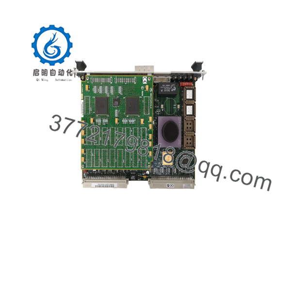
MVME167-33B
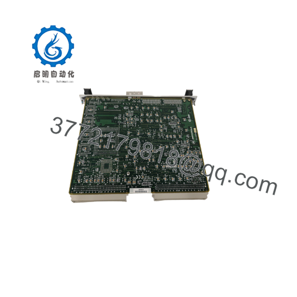
MVME167-33B
Troubleshooting Quick Reference
| Symptom | Possible Cause | Relevance to this Part | Quick Check Method | Recommendation |
| FAIL LED Lit Red on Boot | Power rail out of tolerance or DRAM parity error | ✅ High | Measure +5V DC rail at backplane P1 pins 1/2 with a multimeter; verify it stays within 4.85V–5.25V. | Check VME power supply output before replacing board hardware. |
| VME Bus Access Error (BERR) | Incorrect slot placement or missing VME system controller | ❓ Medium | Ensure board is in Slot 1 if designated as System Controller; verify VMEchip2 jumper settings. | Enable System Controller jumper on Slot 1 card or insert missing bus grant jumpers on adjacent slots. |
| No Serial Console (167Bug) Output | Incorrect DB-25/DB-9 serial cable pinout or baud mismatch | ❌ Low | Connect oscilloscope to Serial Port 1 TX pin while pressing front-panel RESET button. | Verify terminal program is set to 9600-8-N-1 and use a true MVME712 transition module or null-modem cable. |
| NVRAM Clock Loss / Settings Lost | Internal battery depletion on DS1284 RTC IC | ✅ High | Check if system time resets to epoch on power cycle; measure voltage on RTC chip pin. | De-solder and replace the socketed DS1284 real-time clock/NVRAM module. |
| SCSI Device Not Found on Boot | Missing SCSI active termination on transition board | ❌ Low | Inspect SCSI bus cabling for proper 110Ω active termination at physical cable ends. | Ensure transition module (e.g., MVME712M) has active SCSI terminators installed. |
Note: If your system fails to pass the onboard 167Bug diagnostic test suite, capture the serial console boot record and contact our engineering support team.
Frequently Asked Questions (FAQ)
Q: What does the “-33B” designation indicate in the model number?
A: The “-33” indicates a 33 MHz MC68040 processor speed rating (compared to lower-frequency 25 MHz variants). The “B” suffix designates a specific factory revision hardware layout, typically referencing memory mezzanine density and updated VMEchip2 ASIC silicon.
Q: Can I use this board as a standalone controller without a VME backplane?
A: No. While the MVME167-33B can execute code independently once powered, it relies on the DIN 41612 P1 and P2 backplane connectors for stable +5V and ±12V DC power distribution and system grounding.
Q: Does the MVME167-33B require an external transition module for I/O pinouts?
A: Yes. In standard 6U VME chassis installations, serial, Ethernet, and SCSI signals pass through the P2 backplane connector to an external transition module such as the Motorola MVME712M, MVME712A, or MVME761. Connecting directly to the front panel only provides debug terminal access.
Q: How do I back up the configuration settings stored in NVRAM?
A: NVRAM data is preserved by an onboard lithium cell within the Dallas RTC chip. Before replacing a board, dump the environment parameters by logging into the 167Bug system monitor via serial console and running the ENV command to print all network, boot device, and SCSI parameters.
Q: Are these boards original OEM units, and how are they verified?
A: Every MVME167-33B unit is original Motorola factory-manufactured hardware. Because the series is mature, stock consists of New Surplus (unused original spares) and Refurbished boards that undergo full component-level inspection, EPROM verification, and 24-hour diagnostic testing on an active VME chassis bench.
SOP Quality Control Process
1. Inbound Inspection & Traceability
- Authentic Motorola serial tag, barcode, and PCB mask layer verification.
- Visual inspection under high-magnification for DIN 41612 P1/P2 connector pin damage, PCB solder mask oxidation, and socket lead integrity.
- Inspection of socketed ICs (MC68040 CPU, VMEchip2, boot EPROMs) for thermal discoloration or mechanical stress.
2. Live Bench & Functional Testing
- Installed in a calibrated 6U VME chassis powered by a heavy-duty regulated VME power supply rail.
- Boot testing executed using 167Bug monitor firmware via serial console port.
- 24-hour continuous burn-in memory test running full DRAM read/write cycles, parity generation checks, and stress testing under elevated ambient temperatures.
- SCSI loopback and Intel 82596 Ethernet ping tests verified under active load.
3. Electrical Parameter & Safety Checks
- Measure current draw across +5V, +12V, and -12V DC power buses under maximum processing load.
- Ground plane continuity and trace impedance verified using a Fluke 115 multimeter.
4. Firmware & Configuration Verification
- Boot Flash/EPROM firmware checksum verified against factory release files.
- NVRAM battery status checked and 167Bug environment variables reset to standard factory defaults or configured to customer specs.
5. Final QC & Packaging
- Board treated with anti-static spray and sealed inside a moisture-barrier ESD bag with active desiccant.
- Enclosed in high-density anti-static custom foam inside a double-walled corrugated box.
- Signed QA Pass certificate attached detailing serial tracking and burn-in logs.
Technical Pitfall & Survival Guide
- ❗ VMEbus Daisy-Chain Jumper Pitfall: VME backplanes require continuous Bus Grant (BG0–BG3) and Interrupt Acknowledge (IACK) signals across all slots. If you remove an old module and leave an empty slot between cards without installing backplane jumper straps, downstream modules will hang waiting for bus grant tokens.
- ❗ DIN Connector Insertion Pin Bending: The 96-pin DIN 41612 P1/P2 connectors on 6U VME cards are easily damaged if inserted off-angle. Align the card precisely in the chassis card guides and seat the unit using both front-panel ejector handles simultaneously—never force or strike a card into place.
- ❗ ±12V Rail Prerequisite for Serial Comms: The onboard CD2401 serial controller and line drivers require ±12V DC supplied directly from the VME backplane P1 connector. If your chassis power supply drops the 12V rails, the board will boot and run CPU code, but all serial communications will drop offline completely.
- ❗ ESD Vulnerability on Legacy CMOS Circuits: Legacy 68k family CPUs, ASICs, and fast DRAM chips are highly susceptible to static discharge. Always handle the board wearing a grounded ESD wrist strap at an ESD-safe workbench. Never touch edge connector contacts or exposed IC pins with bare hands.



