
 WhatsApp: +86 16626708626
 Email:
  Phone: +86 16626708626
Description
3. Key Technical Specifications
| Parameter | Value |
|---|---|
| Manufacturer | Motorola Computer Group |
| Model | MVME187 |
| Assembly Number | 01-W1629B01B |
| Product Type | RISC Single Board Computer |
| Bus Architecture | ANSI/VITA VMEbus |
| Form Factor | 6U VME Module |
| Processor | Motorola MC88100 RISC CPU |
| CPU Frequency | 25 MHz or 33 MHz (variant dependent) |
| Cache | 16 KB/16 KB or 64 KB/64 KB I/D Cache |
| Memory Support | 4 MB to 256 MB DRAM via mezzanine modules |
| Ethernet | Intel 82596CA LAN Controller |
| SCSI Interface | NCR 53C710 SCSI with DMA |
| Serial Ports | 4 × EIA-232-D |
| Parallel Port | Centronics Compatible |
| Static RAM | 128 KB SRAM |
| Status Indicators | FAIL, STAT, RUN, SCON, LAN, 12V, SCSI, VME LEDs |
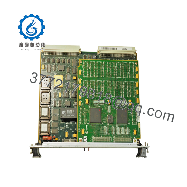
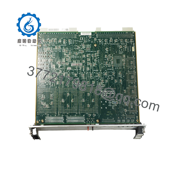
The MVME187 was Motorola’s first VME-based single-board computer built around the M88000 RISC architecture. It combined Ethernet, SCSI, serial communications, and VMEbus control functions on a single processor board.
4. Product Introduction
The Motorola MVME187 01-W1629B01B is a high-performance VMEbus RISC single-board computer designed around the Motorola MC88100 processor. It was widely deployed in telecommunications systems, industrial automation platforms, aerospace test equipment, defense applications, and OEM embedded controllers requiring deterministic operation and long service life.
Unlike earlier 680×0-based VME processors, the MVME187 introduced Motorola’s M88000 RISC architecture while retaining compatibility with existing VME infrastructures. Integrated Ethernet, SCSI, serial communications, and flexible memory expansion made it a practical upgrade path for many VME-based installations.

- MVME 187 01-W1629B01B
- MVME 187 01-W1629B01B
5. Installation & Configuration Guide
Stage 1: Pre-Installation Preparation (10 Minutes)
⚠️ Safety First
- Notify operations personnel of planned downtime.
- Bring the machine or process to a safe operating state.
- Apply lockout/tagout procedures.
- Remove all rack power.
- Wait a minimum of 5 minutes for stored energy to dissipate.
Tools Required
- ESD wrist strap
- PH1 screwdriver
- Fluke 115 multimeter
- Wire labels
- Smartphone camera
- Flashlight
Data Backup
- Back up operating system images.
- Export application files.
- Record Ethernet parameters.
- Document SCSI device IDs and termination settings.
- Photograph all jumper positions.
- Photograph transition module wiring.
Stage 2: Removing the Old Module (5 Minutes)
- Remove chassis access covers.
- Label all field connections.
- Disconnect transition module cables.
- Release board retention hardware.
- Operate both ejector handles evenly.
⚠️ Never pull on one corner of the board. Uneven extraction can damage VME connectors.
- Slide the board straight out.
- Inspect:
- P1/P2 connectors
- Backplane contacts
- Dust buildup
- Corrosion
- Bent pins
⚠️ Keep the original board available until commissioning is complete.
Stage 3: Installing the New Module (10 Minutes)
- Connect ESD protection.
- Verify exact assembly number: 01-W1629B01B
Configuration Clone (Crucial)
- Match all jumpers exactly.
- Verify system controller jumper settings.
- Verify serial clock configuration jumpers.
- Verify memory mezzanine installation.
- Confirm transition board compatibility.
❗ This is the most common rookie mistake, but it happens constantly. Take a picture before you pull it. I can’t stress this enough.
- Insert the board carefully into the VME slot.
- Fully engage ejector handles.
- Secure retaining hardware.
- Reconnect transition board cabling.
Self-Checklist
- Assembly number matches
- Jumpers duplicated
- Memory mezzanine installed
- Connectors fully seated
- Retention hardware secured
Stage 4: Power-On & Testing (15 Minutes)
Pre-Power Check
- Verify no shorts exist on power rails.
- Confirm proper board seating.
- Verify transition board connections.
Power-On Procedure
- Energize the VME chassis only.
- Observe startup LEDs.
- Confirm RUN indicator activity.
- Access the 187Bug monitor.
- Verify Ethernet operation.
- Verify SCSI detection.
- Verify serial communications.
- Perform application startup test.
Troubleshooting Note
⚠️ Solid FAIL LED typically indicates boot firmware, memory, or CPU initialization faults.
⚠️ No Ethernet communication often points to transition module wiring or LAN transceiver issues.
⚠️ If SCSI devices disappear after replacement, verify termination and device ID settings before replacing hardware.
Common Replacement Risks from the Field
❗ Firmware Revision Mismatch
I’ve seen maintenance teams replace a working MVME board only to discover the replacement carried a different 187Bug revision.
The result was two days of troubleshooting and a system that refused to boot correctly.
Avoidance: Document firmware versions before removal and request matching revisions when sourcing spares.
❗ DIP Switch and Jumper Misconfiguration
The MVME187 contains multiple configuration headers.
One misplaced jumper can prevent startup.
Avoidance: Photograph every header before removal and replicate settings exactly.
❗ Transition Module Incompatibility
The MVME187 relies heavily on compatible transition modules such as the MVME712 family for field I/O access.
Avoidance: Verify transition module compatibility before installation.
Warning: Physical connector fit does not guarantee electrical compatibility.
❗ Power Budget Errors
Memory expansion boards and multiple peripherals increase rack power consumption.
Avoidance: Calculate total VME chassis load and maintain at least a 20% reserve margin.
❗ Electrostatic Discharge (ESD)
I once watched a contractor handle a VME processor board during a winter shutdown without a wrist strap. The board failed immediately during startup diagnostics.
Avoidance: Always use grounded ESD protection and handle the board by its edges.
Keep these checks in mind and you’ll save yourself 90% of typical rework time.
6. Frequently Asked Questions (FAQ)
Q1. Can I hot-swap the MVME187?
No.
The MVME187 was not designed for hot-swapping. Removing it under power can corrupt bus transactions, damage hardware, and crash connected systems. Always shut down the VME chassis first.
Q2. Is the MVME187 obsolete?
Yes.
Motorola discontinued the MVME187 many years ago. Most available inventory today comes from surplus stock, decommissioned systems, or professionally refurbished units.
Q3. What processor does the MVME187 use?
The board uses the Motorola MC88100 RISC processor with associated 88200 or 88204 cache/memory management units depending on the specific configuration.
Q4. What memory configurations are supported?
Depending on the installed mezzanine modules, memory capacities range from 4 MB to 256 MB with parity or ECC protection. Two mezzanine modules can be stacked in certain configurations.
Q5. Will I lose my application software when replacing the board?
Not necessarily.
Many systems store applications on SCSI storage devices or external media. However, firmware settings, NVRAM parameters, and boot configuration data should always be backed up before replacement.
Q6. What transition boards work with the MVME187?
Motorola documentation identifies compatibility with:
- MVME712-12
- MVME712-13
- MVME712M
- MVME712A
- MVME712AM
- MVME712B
Always verify the exact installed configuration before ordering.


