
 WhatsApp: +86 16626708626
 Email:
  Phone: +86 16626708626
Description
3. Key Technical Specifications
- Analog Output Channels: 8 channels, independently configurable
- Output Ranges: ±5 V, ±10 V, 0–5 V, 0–10 V per channel
- Resolution: 12-bit DAC
- Linearity Error: ±0.05% full scale
- Settling Time: <10 µs full-scale response
- Output Drift: <5 ppm/°C
- Isolation: 250 V channel-to-channel, 500 V to VMEbus
- Protection: 500 mA short-circuit protection per channel
- Bus Interface: VMEbus A16/D16 slave (IEEE 1014)
- Power Consumption: 7–10 W typical
- Operating Temperature: −20 to +70 °C
- Form Factor: 3U VME module
4. Product Introduction
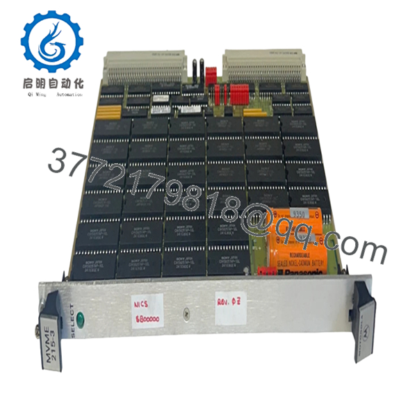
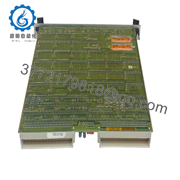
The Motorola MVME215-3 64-W5698B01B Rev. C is a 3U VMEbus analog output module designed for precision actuator control in legacy industrial and test systems. It converts digital setpoints from host SBCs (MVME162, MVME147, etc.) into stable voltage outputs for valves, drives, and servo systems.
In practice, this module is deployed where signal stability matters—closed-loop temperature control, motion systems, or calibration rigs. Compared to mixed I/O cards, this is a dedicated AO design, which avoids channel crosstalk and gives predictable drift performance over long run times.

- MVME215-3 64-W5698B01B
5. Installation & Configuration Guide
Stage 1: Pre-Installation Preparation (10–15 minutes)
- ⚠️ Safety First: Notify operations, shut down rack, lock out/tag out. Wait at least 5 minutes.
- Tools Required: ESD strap, PH1 screwdriver, Fluke 115 multimeter, labels, smartphone
- Data Backup:
- Document VME address mapping (A16 space)
- Record software scaling factors (important for ±10 V vs 0–10 V)
- Photograph any jumper or configuration headers
Stage 2: Removing the Old Module (5–10 minutes)
- Remove front panel screws
- Label all analog output wiring (channel mapping matters)
- Pull using ejector handles evenly
- Inspect DIN connectors for bent pins or oxidation
- ⚠️ Note: Analog modules are sensitive—don’t flex the PCB during removal.
Stage 3: Installing the New Module (10 minutes)
- ESD protection mandatory
- Confirm exact revision: MVME215-3 Rev. C (watch suffix differences)
- Configuration Clone (Critical):
- Match output range settings per channel
- Verify interrupt vector configuration if used
- Insert into correct 3U slot
- Ensure full seating into backplane
- Reconnect analog wiring (check polarity and shielding)
- Checklist:
- Output ranges match
- Wiring polarity correct
- Shield grounding verified
Stage 4: Power-On & Testing (15–20 minutes)
- Pre-check: Measure +5 V rail stability (<±5%)
- Power-On Steps:
- Power rack only
- Check module LEDs (power + channel activity)
- Connect via host CPU (e.g., MVME162)
- Issue test output commands (0%, 50%, 100%)
- Measure output with calibrated voltmeter
- ⚠️ Troubleshooting Note:
- Output offset → calibration drift or reference issue
- No output → check A16 address mapping
- Erratic signal → grounding or shielding problem
6. Frequently Asked Questions (FAQ)
Q1: Can I hot-swap this module?
No. VME systems don’t tolerate hot insertion well. You risk bus faults or damaging the DAC circuitry. Power down first.
Q2: Is this module still manufactured?
No, it’s obsolete. Available units are surplus or refurbished. Stock is inconsistent and getting tighter each year.
Q3: What typically fails on MVME215-3?
The precision voltage reference and DAC stages. After 15–20 years, drift increases. I’ve seen outputs shift by 1–2% if not recalibrated.
Q4: Can I replace it with a newer module?
Not directly. There’s no pin-compatible modern equivalent. Migration usually involves moving to Ethernet-based I/O or custom VME replacements.
Q5: How accurate is this module in real operation?
Nominally ±0.05% FS, but field reality depends on calibration. If the reference is aging, expect drift unless recalibrated.
Q6: Why is channel configuration critical?
Each channel supports multiple voltage ranges. If you mismatch (e.g., 0–10 V vs ±10 V), your actuator response will be completely off. I’ve seen valves slam shut due to this.
Q7: Any field advice before commissioning?
- ❗ Always verify output with a meter before connecting actuators
- ❗ Check shielding—analog noise will bite you
- ❗ Run a 24-hour drift test if process is sensitive
Keep these checks in mind and you’ll avoid most calibration and control instability issues I’ve seen with legacy VME analog systems.


