
 WhatsApp: +86 16626708626
 Email:
  Phone: +86 16626708626
Description
. Key Technical Specifications
- Processor: PowerPC MPC60x / MPC750 family (266–400 MHz depending on variant)
- Architecture: PowerPlus architecture with PCI-VME bridge
- Memory: 64–256 MB SDRAM (expandable via onboard slots)
- Flash Memory: 4–8 MB boot Flash
- NVRAM/EEPROM: ~512 KB configuration storage
- Bus Interface: VME64 (A32/D32, block transfer supported)
- Ethernet: 10/100Base-T interface (RJ45)
- Serial Ports: 2 × RS-232 / RS-422 / RS-485 configurable
- Expansion: Dual PMC (PCI Mezzanine Card) slots
- Timers: Multiple programmable timers + watchdog
- Power Requirements: +5 V DC, ~15–25 W typical
- Form Factor: 6U VME single-slot board
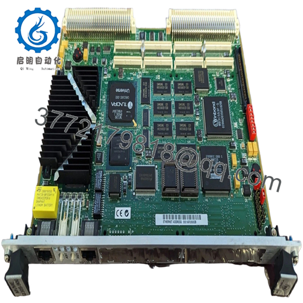
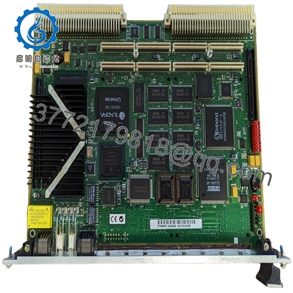
4. Product Introduction
The Motorola MVME2305 is a PowerPC-based VMEbus single-board computer designed as a high-performance CPU module for industrial control, telecom infrastructure, and embedded real-time systems. It replaces earlier 68k-based boards (MVME162/167 series) with a PCI-based architecture and significantly higher processing throughput.
In actual plant environments, this board shows up in later-generation VME systems where deterministic control still matters but higher network throughput and PMC expansion are required. Engineers typically select it when maintaining legacy VME racks while needing better CPU headroom without redesigning the entire system.
- MVME2305
- MVME2305
5. Installation & Configuration Guide
Stage 1: Pre-Installation Preparation (10–15 minutes)
- ⚠️ Safety First: Notify operations, shut down system, apply lockout/tagout. Wait 5 minutes for discharge.
- Tools Required: ESD wrist strap, PH1 screwdriver, Fluke 115 multimeter, labels, smartphone
- Data Backup:
- Backup OS image (VxWorks / pSOS / OS-9 depending on system)
- Record IP address and network config
- Photograph all jumpers (boot source, VME system controller selection)
- Document PMC module configuration if installed
Stage 2: Removing the Old Module (5–10 minutes)
- Disconnect Ethernet, serial, and PMC I/O cables
- Label all connections (especially P2 rear I/O)
- Release ejector handles and pull evenly
- Inspect VME backplane connectors carefully
- ⚠️ Note: VME64 backplanes are less forgiving—misalignment can damage both board and backplane.
Stage 3: Installing the New Module (10–15 minutes)
- Apply ESD protection
- Verify exact model: MVME2305 (check suffix/CPU variant)
- Configuration Clone (Critical):
- Match system controller jumper (J16 typically)
- Set boot Flash bank correctly
- Verify PMC module seating and configuration
- Insert board using guide rails
- Ensure full engagement with backplane connectors
- Secure front panel screws
- Checklist:
- Jumpers match original
- PMC modules secured
- Board fully seated
Stage 4: Power-On & Testing (15–25 minutes)
- Pre-check: Measure +5 V rail stability (±5%)
- Power-On Steps:
- Power rack only
- Observe LED sequence (FAIL → RUN transition)
- Connect to serial console (typically 9600 or 19200 baud)
- Access firmware monitor (PPCBug)
- Verify RAM size and device detection
- Boot OS image
- ⚠️ Troubleshooting Note:
- Stuck in firmware → incorrect boot device or Flash config
- No network → check PHY config or MAC initialization
- Bus timeout → incorrect VME address configuration
6. Frequently Asked Questions (FAQ)
Q1: Can I directly replace an MVME162 or MVME167 with MVME2305?
Not directly. The MVME2305 uses a PowerPC architecture, not 68k. That means different BSPs, different firmware (PPCBug vs MVMEbug), and often OS recompilation. I’ve seen upgrades stall for weeks because of this mismatch.
Q2: Is this module still supported by OEMs?
No. It’s long obsolete. Support is typically internal (your own engineering team) or via third-party specialists.
Q3: Can I hot-swap this board?
No. VME systems generally do not support hot-swapping unless specifically designed with live insertion hardware. Power down to avoid backplane damage.
Q4: What fails most often on MVME2305 boards?
- NVRAM battery-backed RTC
- Ethernet PHY components
- Aging capacitors
I’ve seen boards boot fine but lose configuration every power cycle due to dead NVRAM.
Q5: Why is firmware compatibility critical here?
Because PowerPC boards use PPCBug firmware. If your system expects a specific revision and you install a mismatched one, you’ll get boot failures or device initialization errors.
Q6: How much power margin should I allow?
At least 20% headroom. These boards can draw 15–25 W depending on PMC modules. A fully populated rack adds up quickly.
Q7: Any practical field advice before commissioning?
- ❗ Verify boot source jumpers (Flash vs network boot)
- ❗ Confirm system controller role (only one in rack)
- ❗ Test Ethernet before full integration


