
 WhatsApp: +86 16626708626
 Email:
  Phone: +86 16626708626
Description
3. Key Technical Specifications
| Parameter | Value |
|---|---|
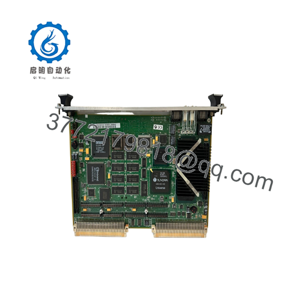
| Model | MVME2307 |
| Processor | Motorola PowerPC MPC604 |
| CPU Frequency | 300 MHz |
| Architecture | 32-Bit PowerPC |
| Form Factor | 6U VMEbus Single Board Computer |
| Memory | 16 MB to 128 MB ECC-Protected DRAM |
| Flash Memory | Up to 5 MB Onboard Flash |
| NVRAM | 8 KB with Battery Backup |
| Ethernet | 10/100 Mbps Auto-Negotiating Interface |
| Serial Ports | One Asynchronous Debug Port |
| PMC Expansion | Two 32/64-Bit PMC Slots |
| PCI Expansion | 64-Bit PCI Mezzanine Connector |
| Timers | Four 32-Bit Timers, One 16-Bit Timer |
| Watchdog Timer | Integrated |
| VME Interface | A32/D32/BLT64 Master/Slave |
| DMA Support | VME D64 and PCI Burst Transfers |
| Interrupt Support | 7-Level Interrupt Handler |
| System Controller | Supported |
| Product Status | Obsolete Legacy Hardware |
The MVME2307 belongs to Motorola’s PowerPlus Architecture family and combines a PowerPC processor, ECC memory subsystem, PCI architecture, PMC expansion capability, Ethernet connectivity, and a high-performance VMEbus interface on a single-slot board.
4. Product Introduction
The Motorola MVME2307 is a high-performance VMEbus single-board computer designed for industrial automation, telecommunications, defense systems, transportation platforms, and scientific instrumentation. It utilizes a 300 MHz PowerPC MPC604 processor and Motorola’s PowerPlus architecture to provide significantly higher processing capability than earlier 68040-based VME systems.
A major advantage of the MVME2307 is its flexibility. The board supports dual PMC expansion modules, ECC-protected DRAM, high-speed DMA transfers, and integrated 10/100 Ethernet, allowing system integrators to add custom I/O while maintaining compatibility with existing VME infrastructure. In many field upgrades, replacing a failed MVME2307 avoids costly software migration and system requalification projects.
- MVME2307
5. Installation & Configuration Guide
Stage 1: Pre-Installation Preparation (10 Minutes)
⚠️ Safety First
- Notify operations of planned downtime.
- Place controlled equipment into a safe operating state.
- Apply Lock-Out/Tag-Out procedures.
- Remove chassis power completely.
- Wait at least 5 minutes for capacitor discharge.
Tools Required
- ESD wrist strap
- PH1 screwdriver
- Fluke 115 multimeter
- Wire labels
- Smartphone camera
- Flashlight
Data Backup
- Backup operating system and application files.
- Record:
- IP address
- Boot parameters
- VME slot location
- Network settings
- Photograph:
- PMC modules
- DIP switches
- Jumpers
- Front-panel cabling
- Record firmware and boot monitor revisions.
Stage 2: Removing the Old Module (5 Minutes)
- Remove front-panel retaining screws.
- Label Ethernet and serial connections.
- Disconnect attached PMC transition cables.
- Release ejector handles.
- Pull the board straight outward.
⚠️ Never twist the board during removal. VME connector damage often causes intermittent faults that appear weeks later.
- Inspect:
- P1 connector
- P2 connector
- Card guides
- Backplane contacts
⚠️ Keep the original board until commissioning is complete.
Stage 3: Installing the New Module (5 Minutes)
Configuration Clone (Critical)
- Connect ESD protection.
- Verify:
- MVME2307 model number
- Assembly number
- Hardware revision
- Replicate all jumper and switch settings.
❗ This is the most common rookie mistake, but it happens constantly. Take a picture before you pull it. I can’t stress this enough.
- Install the board into the VME guides.
- Fully seat the connectors.
- Secure ejector hardware.
- Reinstall PMC modules if used.
Self-Checklist
- Model verified
- Firmware documented
- Jumpers match
- PMC modules installed
- Board fully seated
Stage 4: Power-On & Testing (10 Minutes)
Pre-Power Check
- Verify chassis grounding.
- Measure power rails.
- Check for shorts.
Power-Up Procedure
- Energize the VME chassis.
- Observe status LEDs.
- Verify boot monitor startup.
- Connect through serial debug port.
- Verify Ethernet operation.
- Confirm memory size detection.
- Verify PMC module recognition.
Functional Testing
- Verify VMEbus communication.
- Verify DMA operation.
- Test Ethernet connectivity.
- Check watchdog functionality.
- Run processor load testing.
⚠️ Troubleshooting Note:
- Solid fault LED often indicates firmware incompatibility.
- Ethernet failures frequently result from incorrect boot parameters.
- DMA errors commonly indicate PMC or PCI configuration problems.
Technical Pitfall & Survival Guide
❗ Firmware Revision Mismatch
I’ve seen engineers replace a failed MVME2307 and spend two days troubleshooting what appeared to be a hardware problem.
The real issue was a newer firmware revision that changed boot behavior and Ethernet initialization.
Avoidance:
- Record firmware versions before shutdown.
- Request matching firmware revisions.
- Verify boot ROM compatibility.
❗ PMC Module Configuration Problems
The MVME2307 supports two PMC expansion cards.
I’ve seen replacement projects fail because technicians focused on the CPU board and ignored the PMC configuration.
Avoidance:
- Photograph all PMC hardware.
- Document slot assignments.
- Verify driver compatibility.
❗ VME Slot and Addressing Errors
PowerPlus systems often rely on specific slot assignments and addressing schemes.
Avoidance:
- Record exact chassis position.
- Verify arbitration settings.
- Check system-controller configuration.
❗ Power Budget Miscalculations
A fully populated MVME2307 with two PMC modules can draw significantly more power than earlier CPU boards.
For example, upgrading from an older 68040-based processor board without reviewing power capacity can create unstable startup conditions.
Avoidance:
- Calculate rack power consumption.
- Maintain at least 20% spare capacity.
- Verify cooling airflow.
❗ Electrostatic Discharge (ESD)
I once watched an engineer unpack a PowerPC VME board without an ESD strap during winter maintenance.
The board booted initially, then developed intermittent memory errors during load testing.
The root cause was static damage.
Avoidance:
- Wear a grounded wrist strap.
- Use an ESD work surface.
- Store boards in anti-static packaging.
Keep these checks in mind and you’ll save yourself 90% of typical rework time.
6. Frequently Asked Questions (FAQ)
Q1. What processor does the MVME2307 use?
The MVME2307 uses a 300 MHz PowerPC MPC604 processor and belongs to Motorola’s PowerPlus VME architecture family.
Q2. Is the MVME2307 obsolete?
Yes.
Motorola discontinued the MVME2300 family many years ago. Most available inventory today consists of surplus stock, tested used units, or refurbished boards.
Q3. How much memory does the MVME2307 support?
The platform supports ECC-protected DRAM configurations ranging from 16 MB up to 128 MB, depending on board configuration.
Q4. Can I hot-swap the MVME2307?
No.
The MVME2307 was designed for traditional VMEbus environments. Removing the board under power can disrupt bus arbitration and potentially damage hardware.
Q5. What operating systems commonly run on the MVME2307?
Typical deployments include:
- VxWorks
- pSOS+
- LynxOS
- OS-9
- Embedded Linux
- Proprietary OEM real-time operating systems
Compatibility depends on firmware revision and installed PMC hardware.
Q6. What is the most common replacement mistake?
Firmware mismatch.
I’ve seen projects where a replacement board was physically identical but carried a different firmware revision. The system generated communication faults until the firmware versions were matched.
Q7. Why are MVME2307 boards still purchased today?
Many industrial systems, telecom platforms, and defense applications remain certified around the MVME2307 architecture. Replacing the board is often far less expensive than rewriting software and requalifying the entire system.
Quality Control & Verification Process
1. Inbound Inspection & Traceability
- Verify Motorola labels and part numbers.
- Confirm serial number traceability.
- Inspect for:
- Corrosion
- Rework marks
- Connector wear
- UV discoloration
- Audit accessories and documentation.
2. Live Functional Testing
- Install in a genuine VME test chassis.
- Verify boot monitor operation.
- Test Ethernet communication.
- Verify VMEbus DMA transfers.
- Test PMC slot functionality.
- Run continuous operation for more than 24 hours.
- Generate an official test report.
3. Electrical Parameter Testing
- 500 V insulation resistance test (>10 MΩ target).
- Ground continuity verification.
- Power rail measurements.
- Connector integrity inspection.
4. Firmware & Configuration Verification
- Record firmware revision.
- Photograph jumper positions.
- Verify memory configuration.
- Archive boot parameters.
5. Final QC & Packaging
- QC inspector sign-off.
- Anti-static ESD packaging.
- Bubble-wrap protection.
- Heavy-duty corrugated carton.
- QC Passed label with inspection date.
Test photographs, boot screenshots, and burn-in records should be available upon request. We do not claim failure-proof operation. The objective is to verify that the MVME2307 operates correctly under controlled load testing, including memory diagnostics, Ethernet communication, PMC expansion verification, and VMEbus transaction testing before shipment.


