
 WhatsApp: +86 16626708626
 Email:
  Phone: +86 16626708626
Description
3. Key Technical Specifications
| Parameter | Specification / Value |
| Manufacturer | Motorola Computer Group |
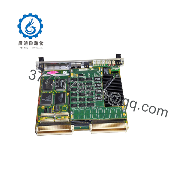
| Model Number | MVME2600-1 |
| Processor Architecture | PowerPC 603 / PowerPC 604e class |
| Local Bus Architecture | 64-bit / 33 MHz Local PCI Bus |
| Memory Bus Speed | 100 MHz System Bus |
| On-Board Base DRAM | Configurable from 32 MB up to 512 MB ECC DRAM via RAM200 expansion |
| Flash Memory | 8 MB surface mount, plus 1 MB socketed in dual PLCC |
| Non-Volatile RAM (NVRAM) | 32 KB (with integrated time-of-day clock and replaceable battery) |
| VMEbus Controller | Tundra Universe ASIC |
| VME Interface Modes | A16–A32, D08–D64, BLT (Burst Transfer), UAT (Unaligned Transfers) |
| PCI Expansion Mezzanine | IEEE P1386.1 compatible 32/64-bit PMC slot |
| Onboard Connectivity Drivers | DEC 21140 Ethernet DMA, Symbios 53C825A Fast SCSI-2 DMA |
| Serial Ports | Dual 16550 compatible asynchronous ports |
4. Product Introduction & Supply Chain Strategy
The Motorola MVME2600-1 is an enterprise-tier PowerPC single-board computer engineered for legacy VMEbus systems. Featuring high-bandwidth architecture driven by a 64-bit local PCI bus and a 100 MHz memory subsystem, this module provides deterministic computational capacity for distributed control systems (DCS), defense radar simulation, and high-speed telemetry applications. It integrates a Tundra Universe interface controller to ensure smooth, high-speed data exchanges across standard VME64 backplanes, supporting burst transfers and complex interrupt handling required by real-time operating systems (RTOS) like VxWorks.
Procuring the MVME2600-1 as New Surplus is a necessary action for plant managers aiming to stabilize their Total Cost of Ownership (TCO). Because this hardware series has been discontinued by the OEM, the market is saturated with worn-out, refurbished boards that are highly vulnerable to internal component degradation, such as flash memory retention loss or aging clock batteries. Investing in a brand new surplus controller card establishes an optimal insurance policy for your facility. It provides guaranteed zero-hour performance, eliminates the risk of immediate bus timeouts, and bypasses long lead times during emergency plant remediation.

- MVME2600-1
5. Installation & Configuration Guide
Stage 1: Pre-Installation (Prep & Safety)
- De-energize the entire VME chassis following plant lock-out/tag-out (LOTO) protocols to isolate all voltage rails.
- Secure a grounded ESD wrist strap to your body and wire it to a bare metal location on the chassis rack frame to discharge ambient static.
- Remove the old controller card and record all layout elements using a high-resolution camera.
- Document the precise orientation of all jumper settings, specifically those mapping the System Controller (SCON) auto-detect, VMEbus mapping, and base memory addresses.
Stage 2: Removal
- Unthread the upper and lower faceplate locking screws anchoring the module to the rack rails.
- Unlatch the upper and lower injector/ejector handles outward to safely break the pin tension from the VME backplane connectors.
- Slide the card out along the guide tracks smoothly, keeping it perfectly level to prevent contact with neighboring modules. Place it directly inside an static-shielding bag.
Stage 3: Installation (Clone & Seat)
- Modify the hardware jumpers on the new surplus MVME2600-1 so they replicate the configuration of the old board down to the individual pin.
- If the legacy installation utilized a PMC mezzanine card for supplementary I/O, transfer it to the new board’s 114-pin expansion connector now, ensuring the 5 V signaling jumpers match.
- Align the card edges with the slot guides and gently slide the board into the rack until it meets the backplane socket.
- Press both front panel levers inward until the module seats firmly, then fasten the top and bottom screws.
Stage 4: Power-On & Testing
- Re-initialize the primary power supply feeds to the VMEbus rack enclosure.
- Check the system diagnostic LEDs on the front panel faceplate. The CPU, PCI, and SCON lamps must indicate correct runtime states, while the red FAIL indicator must switch off post-boot.
- Establish a terminal link via the asynchronous console port to monitor the PPCBug boot monitor handshake and verify the kernel mounts without protocol errors.
6. Firmware/Software Versions & Upgrade Notes
The MVME2600-1 utilizes the legacy Motorola PPCBug firmware environment for self-test diagnostics, hardware initialization, and system bootstrapping. System integration failures are frequently caused by deploying a replacement card whose PPCBug revision does not match the driver expectations of the target real-time operating system (such as VxWorks or OS-9).
Before executing a swap, always query the firmware revision of your existing processor card. If the replacement module contains a newer firmware version (e.g., jumping from a vintage V1.x configuration up to V3.x), the operating system driver may fail to initialize the onboard DEC 21140 Ethernet or Symbios SCSI network controllers due to changed memory map pointers. To guarantee stable operations without extensive software refactoring, you must physically transfer the socketed 1 MB boot ROM EPROMs from your original card over to the empty sockets on the new surplus replacement board.
7. Frequently Asked Questions (FAQ)
Q: Why shouldn’t I just purchase a cheaper refurbished or used MVME2600-1 module?
A: Refurbished and second-hand VME cards pose severe operational risks due to thermal stress and component fatigue from decades of continuous use. They often harbor hidden micro-fractures in solder points or degraded capacitors that fail unpredictably under industrial workloads. A failure on a critical DCS control slot can halt production instantly, costing your operation significantly more than what you save on a discounted component. Our New Surplus inventory provides guaranteed zero-hour components that match OEM-level reliability.
Q: Does this board include the onboard NVRAM battery backup, and is it operational?
A: Yes, the MVME2600-1 includes an integrated NVRAM real-time clock chip with an onboard lithium cell. As part of our comprehensive quality control tracking, we verify that the battery voltage levels are within proper specification to guarantee a data retention lifespan of up to 10 years under continuous system duty cycles.
Q: What is the significance of the System Controller (SCON) jumper setting on this card?
A: The SCON setting configuration determines whether the MVME2600-1 acts as the master arbiter for the entire VMEbus backplane slot layout. If this card is being placed into Slot 1 of your chassis, the SCON jumper must be enabled (or set to auto-detect). If it is placed in any other slot, SCON must be disabled to prevent severe bus communication collisions and immediate system lock-ups.
Q: Can I run this module without an external transition module like the MVME761?
A: While the processor card can operate and manage the VMEbus standalone, its native high-density P2 routing requires an external transition card (such as the MVME761 or MVME712M) to break out connections into standard physical interfaces like RJ-45 Ethernet, DB-9 serial ports, and Centronics parallel connectors. Ensure your existing transition modules and cabling layouts are fully secured before mounting.
Q: What exact warranty policy applies to this New Surplus product?
A: We provide an absolute 1-year warranty on this Motorola MVME2600-1 module. Because this unit is verified New Surplus inventory sourced from secure storage, it contains zero wear on backplane pins and has never been subjected to industrial environments, ensuring a projected active operational lifespan of 10 to 15 years.


