WhatsApp: +86 16626708626
 Email:
 Phone: +86 16626708626
Description
Key Technical Specifications
| Parameter | Value |
|---|---|
| Processor | Motorola PowerPC MPC604e |
| Processor speed | 333 MHz |
| L1 cache | 32 KB instruction / 32 KB data |
| L2 cache | 256 KB external cache |
| Main memory | 128 MB or 256 MB ECC DRAM, configuration-dependent |
| Flash memory | 8 MB onboard Flash; 9 MB total Flash on some configurations |
| VMEbus interface | VME64, A32/D32/D64 master and slave operation |
| PCI architecture | 64-bit PCI through the Raven ASIC |
| PMC expansion | One available PMC slot on the MVME2604 |
| PCI expansion | 64-bit PCI expansion mezzanine connector |
| I/O transition | MVME712-family rear transition module |
| MVME712 I/O | Four multiprotocol serial ports, parallel port, and related peripheral I/O |
| MVME712 power | +5 V, 255 mA typical / 281 mA maximum; +12 V and −12 V also required |
| Front panel | IEEE-style front panel with keyboard, mouse, and floppy interfaces |
| Form factor | 6U VME processor module |
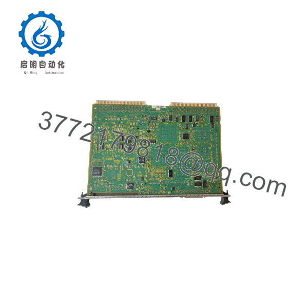
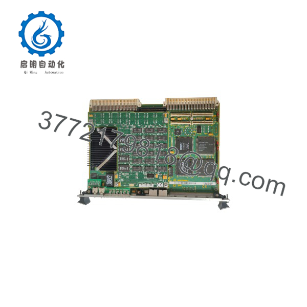
The MVME2604 is a PowerPlus-architecture VME64 processor module; documented configurations include a 333 MHz MPC604e with 128 MB RAM, 8 MB Flash, one available PMC slot, and compatibility with the MVME761 transition module. The “712IO” designation indicates a configuration associated with Motorola’s MVME712 I/O transition module, which brings serial, parallel, and peripheral connections from the processor board’s P2 connector to standard external connectors.
Product Introduction
The Motorola MVME2604-712IO is a 6U VMEbus PowerPC single-board computer configured for use with the MVME712 I/O transition module. It serves legacy industrial-control, data-acquisition, communications, and test systems that require VME64 processing plus conventional serial and peripheral I/O.
The base MVME2604 provides a 333 MHz MPC604e processor, ECC DRAM, Flash storage, PCI/PMC expansion, and VME64 connectivity. Pairing it with the MVME712 transition module preserves the original rear-panel I/O arrangement, which is often the deciding factor when replacing a failed board in an existing Motorola VME chassis.
Troubleshooting Quick Reference
| Symptom | Possible Cause | Relevance to this Part | Quick Check Method | Recommendation |
|---|---|---|---|---|
| No LEDs or no boot activity | Chassis power, fuse, backplane fault, or poor P1/P2 seating | ❌ Low | Measure +5 V, +12 V, and −12 V at the VME backplane; reseat the board with power off | Check PSU, fuses, and both SBC and transition-module seating first |
| Board powers up but will not boot | Corrupt Flash, failed boot device, or firmware/configuration fault | ✅ High | Connect to the serial debug port and capture the boot sequence | Restore firmware or boot image; replace the board if Flash is unusable |
| No serial or parallel I/O | MVME712 transition module, P2 cable, or connector fault | ✅ High | Move the transition module and cable to a known-good MVME2604, or test the SBC without the 712 module | Isolate whether the fault is on the SBC or the I/O transition path |
| No Ethernet link | Cable, switch port, transceiver, or driver/configuration issue | ❌ Low | Swap cable and switch port; verify link LEDs and IP settings | Test networking externally before condemning the board |
| VME bus timeout or bus error | Incorrect address map, bus grant, terminator, or system-controller configuration | ✅ High | Compare VME jumpers and address map with system documentation | Correct configuration first; do not assume a failed CPU board |
| PMC card not recognized | PMC not seated, incompatible PMC, or PCI configuration mismatch | ❌ Low | Power down, reseat PMC, and test it in another known-good MVME2604 system | Verify PMC electrical and software compatibility |
| Random resets or memory faults | Weak RTC battery, overheating, poor contact, or failing ECC DRAM | ✅ Medium | Check battery voltage, clean contacts, verify airflow, and run memory diagnostics | Replace the board if ECC errors persist after environmental checks |
If the fault remains unresolved, send photos of the SBC, MVME712 transition module, chassis, jumper settings, serial boot output, and diagnostic logs before ordering a replacement.
MVME2604-712IO
MVME2604-712IO
Frequently Asked Questions
Can I hot-swap the -712IO?
No. Power down the VME chassis before removing or installing the SBC or the MVME712 transition module. Use a grounded ESD wrist strap and avoid touching connector pins or exposed circuitry.
What exactly is “712IO”?
It refers to an MVME2604 configuration associated with Motorola’s MVME712 I/O transition module. The transition module routes onboard peripheral I/O through the VME P2 connector to standard external connectors, including serial and parallel ports.
Is the -712IO obsolete?
Yes. Motorola originally produced the MVME2600 family, and the product line later passed through Emerson ownership. Original production has ended, so current supply is generally limited to New Surplus, refurbished, or tested pre-owned inventory.
Will it directly replace my existing MVME2604?
Only after matching the exact suffix and hardware configuration. MVME2604 variants differ in CPU speed, DRAM capacity, Flash size, front-panel style, and I/O transition support. Verify the old board’s full model suffix, memory configuration, and installed transition module before ordering.
Will my application software remain after replacement?
Not automatically. The application may reside in Flash, NVRAM, a PMC module, or another storage device in the VME chassis. Back up the boot image, application files, network settings, and VME configuration before removing the old board.
Why is this surplus board less expensive than a new OEM unit?
Because Motorola no longer manufactures it, pricing reflects available surplus inventory rather than current OEM production. New Surplus stock is unused original product; it may have older date codes but should not have field-operating hours.
What should I verify before ordering?
Confirm the required MPC604e clock speed, ECC DRAM capacity, Flash size, front-panel style, PMC hardware, VME address map, and whether your system uses an MVME712, MVME712A/AM, or MVME761 transition module. The MVME712 family requires +5 V, +12 V, and −12 V supplies, with +5 V current specified at 255 mA typical and 281 mA maximum.