WhatsApp: +86 16626708626
 Email:
 Phone: +86 16626708626
Description
Key Technical Specifications
| Parameter | Value |
|---|---|
| Processor | PowerPC 750 (MCP750), 32-bit, 233–366 MHz depending on board revision |
| L1 Cache | 32 KB instruction / 32 KB data |
| L2 Cache | 1 MB backside cache |
| DRAM | 16–256 MB ECC SDRAM onboard; expandable via mezzanine (RAM200: up to 512 MB) |
| Flash Memory | 8 MB onboard + 1 MB socketed (9 MB total on higher configurations; 5 MB on early builds) |
| NVRAM | 8 KB with lithium battery-backed RTC (battery replaceable) |
| VMEbus Interface | Universe II VME64x PCI-to-VME bridge ASIC, A32/D64 MBLT, master/slave |
| PCI Bus | 64-bit PCI local bus; one 64-bit PMC site |
| Ethernet | 10/100 Mbps Ethernet controller on PCI bus |
| SCSI | Ultra Wide SCSI (single-ended; max cable length 15 ft) |
| Serial Ports | 4 ports routed via P2 to the MVME761 transition module (2–3 async, 1–2 sync/async) |
| Front Panel I/O | Keyboard, mouse, floppy/LED headers; Reset and Abort switches; status LEDs |
| Real-Time Clock | Battery-backed, with 8 KB NVRAM |
| Operating Systems | VxWorks, VMEbus-based real-time OS; Motorola PPCBug firmware/debugger |
| Input Power | ‘+5 V, +12 V, −12 V from VME backplane |
| Form Factor | Double-height (6U) VME64x, 160 mm depth |
| Operating Temperature | 0 to +55 °C (free-flow forced air) |
| Humidity | 5–90 % non-condensing |
⚠️ Note: MVME2700 model numbers encode the CPU speed, memory, and I/O configuration (e.g., MVME2700-2361, MVME2700-3361, MVME2700-4361). The “-761” designation refers to the MVME761 transition module I/O configuration. Verify the exact suffix and artwork variant against your installed board and the OEM datasheet before ordering — two artwork variants of the MVME2700 exist and are not always drop-in interchangeable in legacy backplanes.
Product Introduction
The Motorola MVME2700-761 is a 6U VME64x single-board computer built around the PowerPC 750 processor at speeds up to 366 MHz, with 32 KB L1 cache, 1 MB backside L2 cache, and onboard ECC SDRAM up to 256 MB. It serves as the system controller in industrial real-time applications: process control hosts, test and measurement systems, semiconductor equipment, and defense/aerospace platforms running VxWorks-class operating systems.
Its distinguishing feature is the Universe II PCI-to-VME bridge, which gives the board full A32/D64 VME64x master and slave capability, plus a 64-bit PMC slot for expansion. Compared with the older MVME2600 series, the MVME2700 delivers higher PowerPC 750 performance on the same VME footprint — which is why plants keep these chassis alive rather than re-engineering entire VME systems. The MVME761 transition module routes SCSI, serial, and parallel I/O off the P2 connector to real-world connectors.
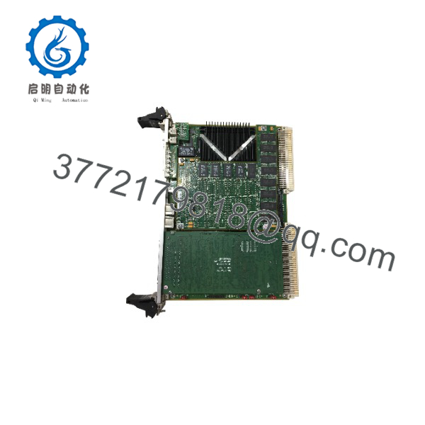
MVME2700-761
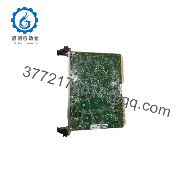
MVME2700-761
Installation & Configuration Guide
Realistic time budget: 45–60 minutes for a board swap, plus application reload. Not 30 — VME systems carry P2 wiring and firmware variables that deserve respect.
Stage 1: Pre-Installation Preparation (10–15 min)
- ⚠️ Safety First: Notify operations of the downtime window. Verify the process is in a safe state. Lock out/tag out the chassis power supply. Wait 5 minutes for backplane capacitor discharge before touching any board.
- Tools Required: Grounded ESD wrist strap, ESD mat, flat-blade screwdriver for injector/ejector handles, Fluke 115-class multimeter, cable labels, camera or smartphone.
- Data Backup — do this before anything else:
- Photograph the front panel, P1/P2 cable positions, and any user-configurable headers or jumpers.
- Record the PPCBug firmware version and the VMEbus settings (system controller jumper, VMEbus time-out, address maps, Universe II register values). If the board is still alive, dump its environment variables (ENV/CNFG) over the serial debug port.
- Back up the application image from Flash and the OS from disk/network boot source. On these boards the application does not always live on the SBC — some sites boot from a SCSI disk or over Ethernet. Know where your image lives before you pull hardware.
- ❗ If the failing board has a suspect NVRAM battery, copy down all stored environment settings — they will be lost when you remove power.
Stage 2: Removing the Old Module (10 min)
- Power down the chassis fully. Do not trust the “soft off” — kill the breaker.
- Disconnect P2 cabling at the MVME761 transition module or cable assembly. Label each cable.
- Loosen both injector/ejector screws alternately and pull the board straight out. Never rock the board sideways in the slot — the 96-pin P1 and P2 connectors on VME64x backplanes bend easily, and a bent P1 pin can take the whole backplane out of service.
- Inspect the backplane slot: dust, bent pins, discoloration. Blow out with dry air if needed.
- ⚠️ Keep the old board on the bench until the replacement passes a full functional test. Its firmware settings and jumper photo are your rollback reference.
Stage 3: Installing the New Module (10–15 min)
- Ground yourself at the bench, board on the ESD mat. Confirm the part number and artwork variant match your old board (e.g., MVME2700-3361 vs -4361 — memory and speed differ).
- Configuration clone: Verify Flash contents, firmware version, and NVRAM environment against your documented baseline. Set the system controller designation to match the chassis (only one board per chassis should be system controller — unless your slot layout requires otherwise).
- Seat the board in the slot. Tighten the two injector/ejector screws evenly, top and bottom, until the connectors seat fully. Uneven tightening cocks the board and stresses P1 pins.
- Reattach P2 cabling and front panel connections per your photos.
Self-checklist: [ ] Part number/variant verified [ ] System controller setting matches [ ] Cables seated per photos [ ] Ejector screws tight, board square in slot
Stage 4: Power-On & Testing (15–20 min)
- Before power-up, meter the +5 V, +12 V, and −12 V rails at the backplane for shorts to ground.
- Power the chassis. On the serial debug port (9,600 baud default on the MVME761), watch for the PPCBug banner. The front panel LEDs should show a normal boot state.
- Verify the firmware version matches your baseline. If the board shipped with a different PPCBug revision, expect changed default environment variables — re-enter your documented ENV settings rather than accepting defaults.
- Restore your application image to Flash or confirm network/SCSI boot.
- Dry-run test: verify Ethernet link, a VMEbus slave window access to a known I/O board, and each serial port on the transition module.
- ⚠️ Troubleshooting note: No PPCBug banner usually means a serial port configuration mismatch on your terminal emulator — check baud rate before panicking. Bus errors during VME access point to the Universe II address window configuration, not necessarily bad hardware. If the board fails after a few minutes of run time, check chassis airflow; the PowerPC 750 relies on forced-air cooling across the heatsink.
Frequently Asked Questions (FAQ)
Q1: Can I hot-swap the MVME2700-761 under power?
No. This is a standard VME64x board, not a live-insertion design. Pulling it while the backplane is powered risks damaging the P1 connector pins and backplane drivers. Kill the chassis power first. Some adjacent boards tolerate it — the VMEbus itself won’t, and neither will your backplane budget.
Q2: Is this model obsolete, and is it genuinely new?
Yes, it’s obsolete — Motorola exited the embedded board business and the MVME line passed to Emerson Embedded Computing (Artesyn), which has since discontinued it. There is no factory-new production. What we sell is New Original / New Surplus: boards in original OEM packaging, sourced with traceable packing lists and customs documentation, serial-verified against counterfeits. Genuinely new-old-stock of this board is getting scarce; some market stock is refurbs sold as new, so ask for the test report and packaging photos. We provide both on request.
Q3: Is the “-761” a different CPU than other MVME2700 models?
The “-761” denotes the I/O configuration with the MVME761 transition module. The base board under it is a standard MVME2700 (PowerPC 750). But within the MVME2700 family, suffix digits encode CPU speed and memory — a -2361 and a -4361 are different animals. Match the full suffix to your installed board. Don’t order from memory; photograph the label.
Q4: Will I lose my program when I pull the old CPU?
The application normally lives in the board’s 8 MB Flash or boots from network/disk. If you’ve backed up the Flash image and the NVRAM environment variables, you lose nothing but uptime. If you haven’t — and the board is already dead — you may be recovering from an off-board copy. This is why I tell every client: image your Flash while the system is healthy, not after it faults. The NVRAM lithium battery on a 20-year-old board is also well past its design life; assume environment variables can vanish at any power cycle.
Q5: What’s the direct replacement if the MVME2700 is out of stock?
There is no true drop-in replacement. The MVME5100 (PowerPC 750 at 400–500 MHz) is the closest functional successor and also uses the MVME761/712M transition modules, but it needs new firmware builds, a different PPCBug revision, and requalification — a migration project, not a swap. For pure form-fit-function, a tested surplus MVME2700 of the same suffix is the only low-risk option. We’ll tell you honestly which we have in stock.
Q6: What condition are your boards in, and how are they tested?
Our incoming inspection covers source traceability (OEM packing lists/customs declarations), serial number and anti-counterfeit verification, and visual inspection for corrosion, rework marks, or UV yellowing. Every board gets a live functional test on a genuine VME64x test chassis: power-on self-test and PPCBug banner verification on the debug serial port, DRAM ECC and Flash diagnostics, Ethernet loopback, SCSI detection, and a minimum 24-hour powered soak with thermal monitoring. Electrical parameters are verified with a 500 V Megger (>10 MΩ insulation) and rail voltage measurement with a Fluke multimeter. Firmware version and NVRAM contents are documented and photographed. Each unit ships in ESD bagging with a dated QC Passed label and a full test report. Test photos and videos are available on request.
Q7: Why is your price lower than the original OEM list price?
Because the OEM no longer manufactures or supports this board — list price is a historical number, not a market one. New Surplus stock was acquired through authorized distribution closures and OEM excess inventory, so we price against actual market availability rather than 2000-era list pricing. We state the condition plainly: New Surplus, tested, 1-Year Warranty. If a unit is Refurbished (tested) rather than new surplus, we say so on the listing. No mystery grades.