
 WhatsApp: +86 16626708626
 Email:
  Phone: +86 16626708626
Description
3. Key Technical Specifications
| Parameter | Value |
|---|---|
| Manufacturer | Motorola Computer Group |
| Model | MVME337-1 |
| Daughtercard Assembly | 01-W3486B03A |
| Product Type | VMEbus Controller Module |
| Processor | Motorola MC68020 |
| CPU Frequency | 20 MHz |
| Bus Architecture | ANSI/VITA VMEbus |
| Secondary Bus | VSBbus (VME Subsystem Bus) |
| Form Factor | Double-Height, Single-Width VME Module |
| Memory Configuration | 1 MB or 4 MB Shared DRAM |
| Serial Interfaces | 2 × Front Panel RS-232 Ports |
| Data Width | 32-Bit |
| Address Width | 32-Bit |
| Front Panel Controls | Abort and Reset Switches |
| Application | Communication Processing, Multiprocessor Systems |
| Product Status | Obsolete / Legacy Platform |
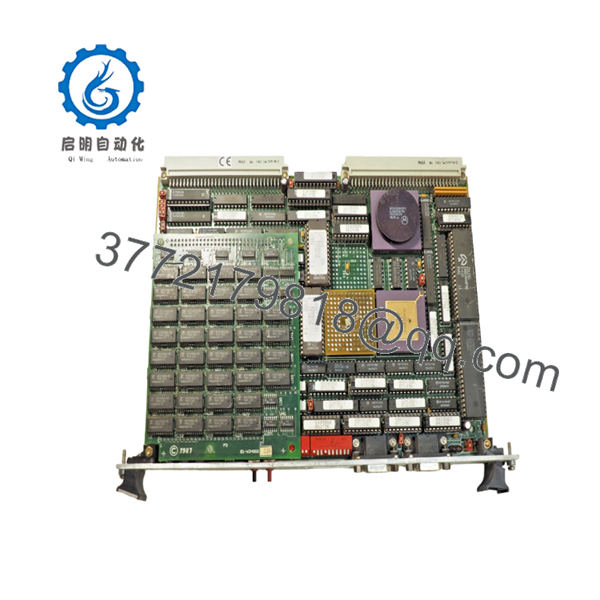
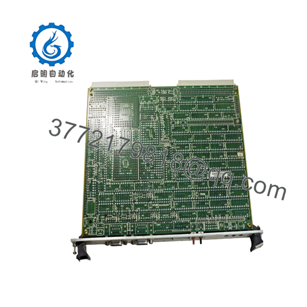
The MVME337-1 is built around the Motorola MC68020 microprocessor and provides both VMEbus and VSBbus interfaces. Known configurations include 1 MB and 4 MB DRAM variants, while the 01-W3486B03A assembly is documented as a daughtercard associated with specific MVME337-1 hardware revisions.
4. Product Introduction
The Motorola MVME337-1 (01-W3486B03A) is a VMEbus controller module designed for industrial communication processing and distributed multiprocessor systems. The board combines a Motorola MC68020 processor, shared DRAM architecture, VMEbus connectivity, and VSBbus communication capabilities in a single VME form factor.
In field installations, the MVME337 often served as an I/O engine or communications controller rather than a primary machine controller. It was commonly deployed in telecommunications equipment, industrial data acquisition systems, and custom OEM embedded platforms requiring coordinated communication between multiple VME processors.
- MVME337-1 01-W3486B03A
- MVME337-1 01-W3486B03A
5. Installation & Configuration Guide
Stage 1: Pre-Installation Preparation (10 Minutes)
⚠️ Safety First
- Notify operations personnel of planned downtime.
- Place the process or machine in a safe state.
- Apply lockout/tagout procedures.
- Remove chassis power completely.
- Wait at least 5 minutes for capacitor discharge.
Tools Required
- ESD wrist strap
- PH1 screwdriver
- Fluke 115 multimeter
- Cable labels
- Smartphone camera
- Flashlight
Data Backup
- Back up communication configuration files.
- Record node addressing information.
- Document serial communication parameters.
- Photograph all jumper settings.
- Photograph attached EVSB or VSBbus modules.
- Record firmware revisions if accessible.
Stage 2: Removing the Old Module (5 Minutes)
- Open chassis access panels.
- Label all communication cables.
- Disconnect external serial connections.
- Release retention hardware.
- Operate ejector handles evenly.
⚠️ Never pry the board from one side. VME connector damage can create intermittent faults that are difficult to diagnose.
- Remove the module in a straight motion.
- Inspect:
- P1 connector
- P2 connector
- Backplane contacts
- Dust accumulation
- Corrosion
⚠️ Keep the original board until the replacement completes functional testing.
Stage 3: Installing the New Module (10 Minutes)
- Attach grounded ESD protection.
- Verify the exact hardware configuration.
Model Verification
- MVME337-1
- Daughtercard: 01-W3486B03A
Configuration Clone (Crucial)
- Replicate all jumper positions exactly.
- Verify VSBbus configuration.
- Verify bus grant/request level settings.
- Verify ROM size selection jumpers.
- Verify timeout and DRAM configuration settings.
The MVME337 family contains multiple configuration headers controlling VMEbus operation, DRAM timing, and bus arbitration. Incorrect settings can prevent startup or communication.
❗ This is the most common rookie mistake, but it happens constantly. Take a picture before you pull it. I can’t stress this enough.
- Insert the board evenly into the VME slot.
- Fully engage ejector handles.
- Tighten retaining hardware.
- Reconnect communication wiring.
Self-Checklist
- Model verified
- Daughtercard verified
- Jumpers duplicated
- Board fully seated
- Wiring secured
Stage 4: Power-On & Testing (15 Minutes)
Pre-Power Check
- Verify no shorts on power rails.
- Confirm board seating.
- Verify communication module connections.
Power-On Procedure
- Energize the VME chassis.
- Observe startup indicators.
- Verify processor initialization.
- Connect diagnostic terminal.
- Verify serial communications.
- Verify VMEbus communication.
- Verify VSBbus operation if used.
- Execute communication diagnostics.
Troubleshooting Note
⚠️ No communication activity often indicates incorrect jumper settings rather than defective hardware.
⚠️ Bus arbitration faults frequently result from incorrect grant/request configuration settings.
⚠️ If communication modules fail to initialize, verify firmware compatibility before replacing hardware.
Common Replacement Risks from the Field
❗ Firmware Revision Mismatch
I’ve seen communication controllers exchanged during shutdowns only to discover the replacement carried different protocol firmware.
The hardware passed diagnostics, but the network would not initialize.
Avoidance: Record firmware versions before removal and request matching revisions.
❗ Jumper Configuration Errors
The MVME337 contains multiple configuration headers controlling bus behavior and memory timing.
One misplaced jumper can disable communication across the entire subsystem.
Avoidance: Photograph every jumper before removal.
❗ EVSB Module Compatibility
The MVME337 often interfaces with EVSB communication modules.
Physical installation may succeed while communication remains nonfunctional.
Avoidance: Verify both controller and expansion module compatibility.
❗ Power Budget Problems
Older VME systems often operate near supply limits.
Additional communication modules increase power consumption beyond the CPU board alone.
Avoidance: Calculate total rack load and maintain a 20% reserve margin.
❗ Electrostatic Discharge (ESD)
I once watched a technician swap a communications controller during a winter maintenance outage without grounding himself.
The board passed power-on diagnostics but failed serial communication tests immediately afterward.
Avoidance: Always use a grounded wrist strap and ESD mat.
Keep these checks in mind and you’ll save yourself 90% of typical rework time.
6. Frequently Asked Questions (FAQ)
Q1. Can I hot-swap the MVME337-1?
No.
The MVME337 was designed long before modern hot-swap architectures became common. Removing the module under power can interrupt VMEbus and VSBbus transactions and potentially damage hardware.
Q2. What exactly is the 01-W3486B03A?
The 01-W3486B03A is a daughtercard assembly associated with specific MVME337-1 hardware configurations. Available service documentation links this assembly number to MVME337-1 controller modules equipped with MC68020 processors and shared DRAM architectures.
Q3. Is the MVME337-1 obsolete?
Yes.
The MVME337 family is a legacy Motorola VME platform that has been out of production for many years. Current availability is generally limited to surplus inventory and professionally refurbished stock.
Q4. What was the primary purpose of the MVME337?
Unlike general-purpose VME CPU boards, the MVME337 was frequently deployed as an I/O engine and communication processor. It executed protocol software for EVSB communication modules and coordinated communications across VME-based systems.
Q5. Will replacing the board erase my application software?
Not necessarily.
Many installations downloaded communication software from host processors or stored it in EPROM devices. Always back up firmware and configuration data before replacement.
Q6. Why are matching jumper settings so important?
The MVME337 uses jumper-selectable settings for:
- Bus arbitration
- Memory timing
- ROM configuration
- Timeout behavior
- Resource mapping
A single incorrect setting can prevent communication or system startup.


