
 WhatsApp: +86 16626708626
 Email:
  Phone: +86 16626708626
Description
Key Technical Specifications
| Parameter | Specification Value |
|---|---|
| Catalog Number | MVME5100-0161 |
| Central Processor (CPU) | Motorola MPC7410 PowerPC with AltiVec Vector Engine @ 450 MHz |
| L2 / L3 Cache | 2 MB L3 Cache on 200 MHz private bus; 256 KB L2 internal cache |
| System Memory | 512 MB ECC SDRAM (100 MHz bus) on onboard mezzanine board |
| System Bus Bridge | Hawk PCI Host Bridge / Memory Controller ASIC |
| VMEbus Controller | Tundra Universe II ASIC (VMEbus A32/A24/A16, D64/D32/D16, VME64 Master/Slave) |
| PMC Expansion Slots | 2 x 64-bit IEEE 1386.1 PMC slots (33/66 MHz PCI interface) |
| Network Controllers | 2 x 10/100Base-TX Fast Ethernet channels (Intel 82559) |
| Serial Ports | 4 x Asynchronous Serial Ports (RS-232 / RS-422 configurable) |
| Boot Flash Memory | 17 MB Flash Memory (16 MB main bank + 1 MB boot bank) |
| Form Factor | Double-Height Eurocard (6U VMEbus format, 160 mm x 233.4 mm) |
| Power Requirements | +5 V DC @ 4.8 A (Typical); +3.3 V DC @ 3.0 A; ±12 V DC for serial/PMC |
Product Introduction
The Motorola MVME5100-0161 represents the flag-ship PowerPlus II family architecture for 6U VMEbus computing. Powered by a 450 MHz MPC7410 PowerPC processor featuring integrated AltiVec vector processing, 2 MB of L3 cache, and 512 MB of ECC-protected SDRAM, this board provides floating-point math performance and data throughput for radar, medical imaging, defense automation, and industrial control.
Engineered around the Hawk PCI bridge and Tundra Universe II VMEbus controller, the MVME5100-0161 delivers full VME64 compliance alongside dual 64-bit PMC extension slots for custom I/O cards. It natively supports real-time operating systems like VxWorks, LynxOS, and Wind River Linux, making it the primary drop-in replacement solution for legacy VME systems upgrading from earlier MVME2600, MVME2700, or lower-clocked MVME5100 configurations.
Troubleshooting Quick Reference
| Symptom | Possible Cause | Relevance to this Part | Quick Check Method | Recommendation |
|---|---|---|---|---|
| FAIL LED Steady Red on Power-Up | Backplane 3.3V or 5V rail out of specification | ✅ High | Measure backplane voltage using a digital multimeter; check 3.3V supply (must be 3.15V–3.45V). | Adjust or replace the VME system power supply before replacing SBC hardware. |
| PPCBug Diagnostic Halts (RAM Fault) | ECC memory mezzanine unseated or corrupted SDRAM | ✅ High | Reseat the 512 MB memory mezzanine board; check mounting standoff torque. | Run PPCBug RAM diagnostic utility; replace mezzanine if ECC uncorrectable errors persist. |
| No Serial Debug Output (COM1) | Terminal baud mismatch or non-null-modem serial cable | ❌ Low | Scope TX pin on COM1 DB-9/RJ45 connector while cycling power. | Set terminal to 9600-8-N-1; verify RS-232 transmit/receive lines on your break-out cable. |
| VME Bus Access Error (BERR) | Board not in Slot 1 while acting as System Controller | ❓ Medium | Check VMEbus System Controller setting in MOTLoad / PPCBug configuration menu. | Set board to Auto-System Controller or ensure physical placement in VME Slot 1. |
| PMC Module Not Recognized | PMC PCI voltage key mismatch (3.3V vs. 5V VIO) | ✅ High | Check PMC card keying holes and ensure VIO jumpers on MVME5100 match PMC card rating. | Move PMC VIO selector header to match the required 3.3V or 5V signaling voltage. |
Note: If your board halts at the MOTLoad/PPCBug prompt, collect your serial boot logs and contact our technical engineering team.
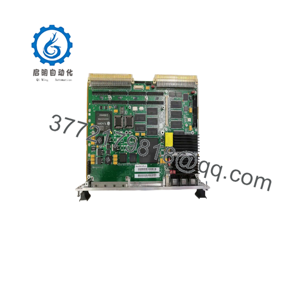
MVME5100-0161
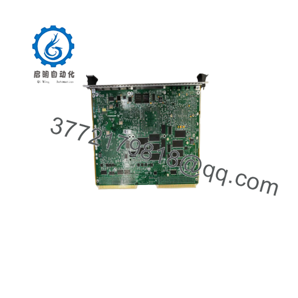
MVME5100-0161
Frequently Asked Questions (FAQ)
Q: What does the specific “-0161” suffix designate on the ?
A: The “-0161” part number specifies a 450 MHz MPC7410 PowerPC processor, 2 MB of L3 cache, 512 MB of ECC SDRAM, 17 MB Flash memory, dual PMC slots, and standard commercial temperature range (0°C to 55°C).
Q: Can I replace an older MVME2600 or MVME2700 board with an -0161?
A: Yes, in most applications. The fits into standard 6U VME64 backplanes. However, you must verify that your VME chassis backplane supplies a dedicated +3.3V DC power rail, as the PowerPC 7410 and Hawk ASIC draw significant current from the +3.3V bus (unlike older 68k boards that ran strictly on +5V).
Q: How do I access the onboard boot diagnostics?
A: Connect a terminal cable to the front-panel serial port (COM1) set to 9600 baud, 8 data bits, no parity, 1 stop bit. Upon powering up, interrupt the boot sequence to enter either the legacy PPCBug monitor or the newer MOTLoad firmware utility to execute hardware self-tests.
Q: Are PMC modules installed on this card compatible with P2 rear I/O routing?
A: Yes. The -0161 routes PMC Slot 1 I/O signals directly to the 5-row 160-pin VME64x P2 connector. Ensure your rear transition module (RTM) pinout matches the Motorola P2 I/O mapping standard before powering up the rack.
Q: How do you verify condition and functionality on surplus cards?
A: “New Surplus” units are unused OEM stock from plant reserves. “Refurbished” cards undergo high-magnification solder inspection, thermal pad replacement, voltage rail checks, and a 24-hour continuous PPCBug stress test in an active VME64x chassis bench. All shipments include a serial-tracked QA Test Certificate.
SOP Quality Control Process
1. Inbound Inspection & Traceability
- Authentic Motorola serial tag, barcode, and PCB assembly layer verification.
- Visual inspection under high magnification for DIN 41612 P1/P2 connector pin damage, PMC socket integrity, and surface-mount capacitor health.
- Inspection of 512 MB SDRAM mezzanine board connectors and standoff mechanics.
2. Live Bench & Functional Testing
- Seated in an active 6U VME64x chassis backed by a regulated power supply (+5V, +3.3V, ±12V).
- Boot testing executed via MOTLoad/PPCBug monitor on serial COM1 console.
- 24-hour continuous memory burn-in test using PPCBug memory diagnostics to stress 512 MB ECC SDRAM under elevated ambient temperature.
- Dual 10/100 Ethernet ports and PMC PCI bus communication verified under active packet load.
3. Electrical Parameter & Safety Checks
- Measure current draw on +5V, +3.3V, +12V, and -12V DC power buses under maximum CPU processing load.
- Ground plane continuity and trace impedance verified using a Fluke 115 multimeter.
4. Firmware & Configuration Verification
- Firmware version documented; MOTLoad/PPCBug boot Flash verified for checksum matching.
- Onboard NVRAM parameter settings cleared and reset to factory baseline defaults.
5. Final QC & Packaging
- Unit treated with static dissipative material and sealed inside a moisture-barrier ESD bag with active desiccant.
- Encased in high-density anti-static custom foam inside a heavy-duty corrugated box.
- Signed QA Pass certificate attached with full serial tracking records.
Technical Pitfall & Survival Guide
- ❗ Missing +3.3V DC Rail Trap: Older VME chassis designed for 68k boards (like MVME147/167) often lack a +3.3V power supply module on the backplane. Placing an into a 5V-only backplane without a +3.3V rail will cause a permanent FAIL LED condition and prevent processor boot entirely.
- ❗ P2 Rear I/O Pin Strain: The 5-row VME64x P1/P2 DIN connectors use high-density pins. Inserting the -0161 into an unaligned backplane card-slot can bend outer ground shield pins. Always use the front panel ejector handles to seat the card squarely into the chassis—never force or strike the card faceplate.
- ❗ PMC Signaling Voltage (VIO) Selection: The provides configurable VIO headers for PMC slots (3.3V vs. 5V signaling). Setting the VIO jumper to 5V while plugging in a 3.3V-only PMC expansion card can destroy the PCI bridge controller on the mezzanine card during power-on.
- ❗ ESD Hazard on PowerPC Silicon: The MPC7410 CPU and Hawk ASIC contain dense 0.18-micron CMOS transistors that are extremely sensitive to electrostatic discharge. Always wear a grounded ESD wrist strap when handling the card or installing PMC modules. Never touch edge-connector contacts directly with bare hands.



