
 WhatsApp: +86 16626708626
 Email:
 Phone: +86 16626708626
Description
Key Technical Specifications
| Parameter | Value |
| Microprocessor | PowerPC G4 (MPC7410) RISC processor at 400 MHz |
| Level 1 Cache | 32 KB instruction cache / 32 KB data cache |
| Level 2 Cache | 2MB backside L2 cache |
| System Memory (SDRAM) | 512MB on-board ECC SDRAM (100 MHz bus) |
| Flash Memory | 17MB total (16MB surface-mount + 1MB via sockets) |
| VMEbus Interface | Tundra Universe II PCI-to-VME bridge, A32/D32/BLT64 |
| Ethernet Interface | Dual Intel 82559ER 10/100 Mb/s Ethernet controllers |
| Mezzanine Expansion | Two IEEE P1386.1 compliant 32/64-bit PMC slots |
| Serial Ports | Two 16550-compatible asynchronous serial ports |
| Non-Volatile Storage | 32 KB NVRAM with time-of-day clock and battery backup |
| Front Panel Type | Scanbe style front panel (-21xx configuration) |
| Operating Temperature | 0 to +55°C (Requires forced air cooling min. 400 LFM) |
| Power Requirements | +3.3V, +5V, +12V, −12V DC backplane supply |
Product Introduction & Supply Chain Strategy
The Motorola MVME51105E-2161 is a 6U VMEbus single-board computer driven by a 400 MHz PowerPC G4 processor and structured around the PowerPlus II architecture. It delivers full PCI throughput natively without starving the processor from its main memory, making it ideal for high-throughput data acquisition in defense, medical imaging, and heavy industrial automation. The “-2161” build features 512MB of ECC SDRAM and a Scanbe front panel layout, providing seamless drop-in form-fit replacement capability for older VME infrastructures.
Securing this module as a Brand New Surplus unit protects plant operations from the severe vulnerabilities of the open secondary market. Because this hardware class is long discontinued by the OEM, used or repaired boards often hide thermal fatigue, degraded traces, and worn backplane pins. Deploying certified New Surplus inventory guarantees OEM-level reliability, eliminates costly unexpected downtime, and preserves long-term capital efficiency by keeping Total Cost of Ownership (TCO) under strict control.
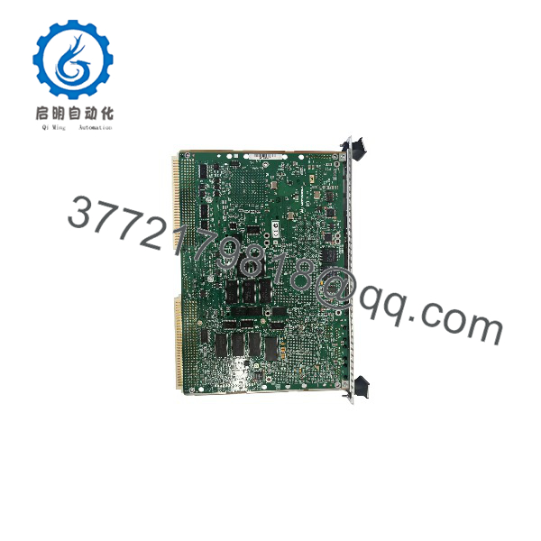
MVME51105E-2161
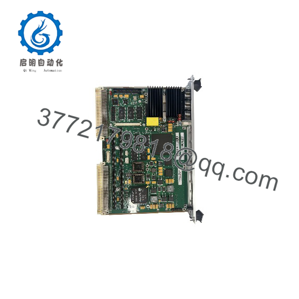
MVME51105E-2161
Installation & Configuration Guide
Stage 1: Pre-Installation (Prep & Safety)
- Execute plant Lock-Out/Tag-Out (LOTO) protocols for the targeted VME chassis.
- Put on an ESD-safe grounded wrist strap before handling electronic components.
- Document all existing front-panel cable attachments and record current onboard switch, jumper, and P2 I/O configurations.
Stage 2: Removal
- Unlatch the top and bottom front-panel injector/ejector handles to disengage the module from the VME backplane P1/P2 connectors.
- Slide the card smoothly out of the chassis guide slots, ensuring no impact to adjacent circuit boards or backplane pins.
Stage 3: Installation (Clone & Seat)
- Replicate all jumper settings and switch positions exactly from your pre-installation documentation onto the new MVME51105E-2161 module.
- Align the board edges with the top and bottom card rails of the target slot.
- Push the module evenly into the rack until the connectors seat firmly, then close the ejector handles to lock the board in place.
Stage 4: Power-On & Testing
- Re-energize the rack and monitor the front-panel status LEDs during the boot self-test sequence.
- Access the onboard debug monitor via the front serial port to verify hardware initialization and memory health.
- Load the operational system image, check network handshakes, and confirm healthy communication loops across the VMEbus backplane.
Firmware/Software Versions & Upgrade Notes
- Recommended Firmware: Pre-loaded boot monitor firmware matching your existing Board Support Package (BSP) and application binary baseline.
- Compatibility Warnings: Verify that your operating system image supports the 400 MHz processor frequency and memory map. Upgrading kernel versions without matching BSP revisions can cause bus timeouts or network driver failures.
- Upgrade Risk Advisory: Avoid flashing firmware updates during active production cycles. Always flash and validate software changes on a secure bench-test rack prior to live installation.
Frequently Asked Questions (FAQ)
Why is this unit priced higher than refurbished alternatives found online?
Our pricing reflects the explicit cost of securing genuine New Surplus inventory globally. While refurbished alternatives may look attractive upfront, they introduce high risk. Our inventory guarantees zero operational wear, original anti-static packaging, and complete operational peace of mind.
Is this unit an original factory-sealed part?
Yes. This product is a Brand New Surplus unit. It has never been deployed in an active plant, never pulled from a decommissioned system, and never repaired. It arrives in original manufacturing condition with clean, un-worn backplane pins.
What is the obsolescence status of the MVME51105E-2161?
This module is officially obsolete and out of production. Because active factory channels are closed, holding 1-2 new units on-site as buffer stock is critical to avoid lengthy downtime when legacy hardware fails.
Can I hot-swap this VME processor module?
No. VMEbus architecture and physical pin connections do not permit safe live insertion or extraction. You must power down the entire VME chassis before servicing or replacing this module.
Will my application binaries and configurations be retained?
The board ships with standard diagnostic monitor firmware. User programs, operating system images, and network configurations must be loaded post-installation. Non-volatile parameters are stored in the on-board NVRAM.
What warranty terms apply to this New Surplus module?
This unit includes a comprehensive 1-year replacement warranty, validating our commitment to uncompromised industrial reliability and supply-chain transparency.



