
 WhatsApp: +86 16626708626
 Email:
  Phone: +86 16626708626
Description
Key Technical Specifications
| Parameter | Specification Value |
| Part / Model Number | MX603-0308-613 / MX603-0308-613A |
| Manufacturer | MOX Automation |
| Module Type | Industrial Control / Communication Interface Card |
| Mounting Style | Rack / Chassis Sub-rack Mount |
| Operating Temperature | -10°C to +60°C (14°F to 140°F) |
| Storage Temperature | -40°C to +85°C (-40°F to 185°F) |
| Signal Isolation | Optical / Galvanic Channel-to-Backplane Isolation |
| Power Supply | Backplane powered or dedicated system bus |
| Status Indicators | Onboard Diagnostic LEDs (Power, Run, Fault, Channel Status) |
| Target Applications | Heavy industry, power generation, metal smelting, and water treatment |
Product Introduction
The MOX MX603-0308-613 is an industrial automation and control module engineered for critical process control, power utility sub-racks, and manufacturing systems. Built to operate reliably in harsh industrial environments, this module handles signal conditioning, I/O interfacing, and communication data transfer within MOX automation racks.
It features robust channel isolation to prevent ground loops and high-voltage transients from reaching core processor backplanes. The MX603-0308-613 is widely deployed in power, metallurgical, and heavy production lines where field reliability and zero-downtime performance are required. It serves as a direct drop-in replacement during system revamps or emergency spares swaps.
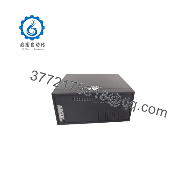
MX603-0308-613
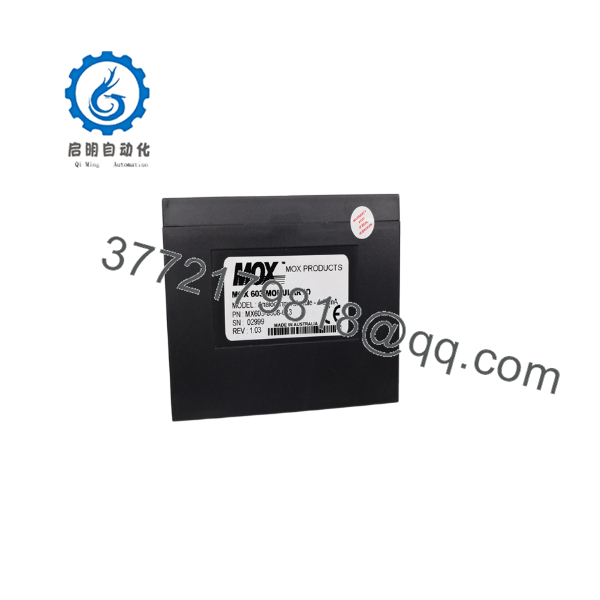
MX603-0308-613
Troubleshooting Quick Reference
| Symptom | Possible Cause | Relevance to this Part | Quick Check Method | Recommendation |
| Module Power / Run LED Off | Missing rack power supply or poor backplane connector seating | ❌ Low | Measure system bus voltage at the chassis backplane using a multimeter. | Reseat the card or check main rack PSU output fuses before replacing hardware. |
| Fault LED Lit Steady Red | Internal logic error or channel overcurrent condition | ✅ High | Check status LEDs on front panel and review controller event logs. | Cycle system power; if fault persists across reboots, hardware replacement is required. |
| Intermittent Signal Loss | Loose field wiring terminals or noise interference | ❓ Medium | Inspect wiring harness connections and check ground shield continuity. | Tighten terminal block screws and ensure signal shield grounding is intact. |
| Channel I/O Error Code | Sensor out-of-range or field device power failure | ❌ Low | Measure voltage/current levels directly at field wiring terminals. | Verify external field transmitter power before condemning the module input channel. |
| Communication Timeout | Baud rate / address misconfiguration on system rack | ✅ High | Verify dip-switch positions or software node settings match system topology. | Confirm address and communication parameters in the master control software. |
Note: If you encounter recurring module faults, document your diagnostic software logs and front-panel LED states, then contact our engineering support team.
Frequently Asked Questions (FAQ)
Q: Is the MX603-0308-613A interchangeable with the MX603-0308-613?
A: Yes. The “A” revision designation typically indicates a secondary factory revision (such as updated PCB component layout or improved noise suppression) while maintaining 100% form, fit, and functional backward compatibility with the original MX603-0308-613 model.
Q: What industrial industries commonly use this MOX module?
A: MOX control modules are widely deployed in heavy-duty process control systems, including power generation plants, steel and aluminum smelting, refrigeration systems, construction machinery, and industrial water treatment facilities.
Q: Do I need special software to configure this card during a swap?
A: The module reads its configuration parameters from the main system rack controller upon boot-up. Ensure any physical address jumpers or configuration DIP switches on the new module mirror your old unit before slotting it into the rack.
Q: Can I hot-swap this module while the system rack is powered?
A: Unless your specific chassis sub-rack documentation explicitly supports Remove and Insert Under Power (RIUP), power down the rack segment before pulling or inserting the card to avoid transient voltage spikes on the backplane.
Q: How do you verify the condition of New Surplus vs. Refurbished units?
A: “New Surplus” modules are unused factory original spares. “Refurbished” units undergo complete physical cleaning, solder joint inspection, and live functional testing on a system test rack. Every module ships with an official serial-tracked QA Test Pass report.
SOP Quality Control Process
1. Inbound Inspection & Traceability
- Authentic MOX label, serial tag, and part number verification against OEM specifications.
- Visual inspection under high magnification for backplane pin bending, solder mask discoloration, or mechanical casing cracks.
- Verification of accessory terminal blocks and hardware latch integrity.
2. Live Bench & Functional Testing
- Inserted into a live test rack powered by regulated industrial power supplies.
- Power-on diagnostic sequence executed to verify LED status indicator functionality.
- Signal acquisition and transmission testing conducted across all active input/output channels.
- Continuous 24-hour load and burn-in testing under simulated field operating conditions.
3. Electrical Parameter & Safety Checks
- Channel-to-backplane optical isolation testing to ensure transient protection.
- Ground plane continuity checked using a Fluke multimeter across chassis clips and ground terminals.
4. Firmware & Configuration Verification
- Firmware revision cataloged and documented.
- Non-volatile configuration memory cleared or set to standard factory default states.
5. Final QC & Packaging
- Treated with static-dissipative spray and sealed inside an anti-static ESD shielding bag.
- Enclosed in heavy-duty corrugated boxing with custom foam cushioning.
- Official QA Pass certificate attached with full serial tracking records.
Technical Pitfall & Survival Guide
- ❗ Address Jumper Misconfiguration: Before installing the replacement card, take a clear photo of the DIP switch and jumper settings on your old board. Installing a new module with default factory switches will cause communication node collisions on the system bus.
- ❗ Field Wiring Short Circuit Hazard: Always measure field loop voltage and check external wiring for short circuits before landing wires on the module’s terminal blocks. A shorted field transmitter can fry the input interface transceivers instantly upon power-up.
- ❗ Backplane Connector Pin Alignment: When sliding the card into the chassis sub-rack, ensure the card guide rails align precisely. Forcing the module when misaligned will bend backplane connector pins, leading to intermittent power loss or destroyed rack backplanes.
- ❗ ESD Protection During Handling: Static charges can degrade CMOS logic components on industrial circuit cards. Always wear a grounded ESD wrist strap when handling the module, and never touch the gold-plated connector contacts directly with bare hands.



