
 WhatsApp: +86 16626708626
 Email:
  Phone: +86 16626708626
Description
Key Technical Specifications
| Parameter | Value |
|---|---|
| Model | MTL 8201-HI-IS |
| Product family | PAC8000 Process I/O |
| Product type | Eight-channel intrinsically safe analog input module |
| Input channel count | 8 single-ended channels |
| Intended field device | Two-wire 4–20 mA transmitter |
| Nominal input range | 4–20 mA |
| Full input range | 0.5–22 mA |
| HART function | HART pass-through; HART variable and status reporting |
| HART configuration | Enable or disable per channel |
| Input resolution | 16 bits |
| Accuracy at 25 °C | ±20 µA |
| Temperature stability | ±0.006% of span per °C from −40 to +70 °C |
| Analog update response | 33 ms maximum to Railbus availability |
| HART response | 0.75 s per channel |
| Minimum transmitter voltage at 20 mA | 15 V |
| Open-circuit indication | Less than 0.5 mA |
| Short-circuit indication | Greater than 21.5 mA |
| Intrinsic-safety classification | [EEx ia] IIC field circuits |
| Per-channel safety output | Uo 28 V; Io 93 mA; Po 0.65 W |
| FM entity parameters | Voc ≤28 VDC; Isc ≤93 mA; Ca ≤0.14 µF; La ≤4.38 mH |
| Channel-to-Railbus isolation | 60 VAC |
| Channel-to-channel isolation | None |
| IS Railbus consumption | 600 mA typical at eight channels, 22 mA each |
| Maximum internal dissipation | 4.2 W |
| Module key code | A1 |
| Module width | 42 mm |
| Module weight | 260 g |
| Recommended field terminal | 8621-FT-IS |
| Loop-disconnect terminal option | 8622-FT-IS |
The MTL 8201-HI-IS provides eight intrinsically safe, single-ended 4–20 mA inputs for two-wire transmitters. It supplies transmitter loop power internally, supports HART pass-through, and reports HART variables and status data when configured. PAC8000 systems support hazardous-area and intrinsically safe field wiring, but the final certification basis always depends on the complete carrier, terminal assembly, wiring, entity parameters, enclosure, and area-classification design.
Product Introduction
The MTL 8201-HI-IS is an eight-channel intrinsically safe analog input module for the PAC8000 Process I/O platform. It receives 4–20 mA process signals from two-wire transmitters in hazardous locations, including pressure, differential pressure, level, flow, and temperature transmitters with analog current outputs.
Each channel includes intrinsic-safety field circuitry, 16-bit conversion, HART pass-through, programmable alarms, configurable filtering, and line-fault detection. The module supplies at least 15 V to each transmitter at 20 mA, making loop-voltage and cable-resistance checks essential before replacing the card. Use the approved 8621-FT-IS or 8622-FT-IS field terminal and verify all entity parameters.
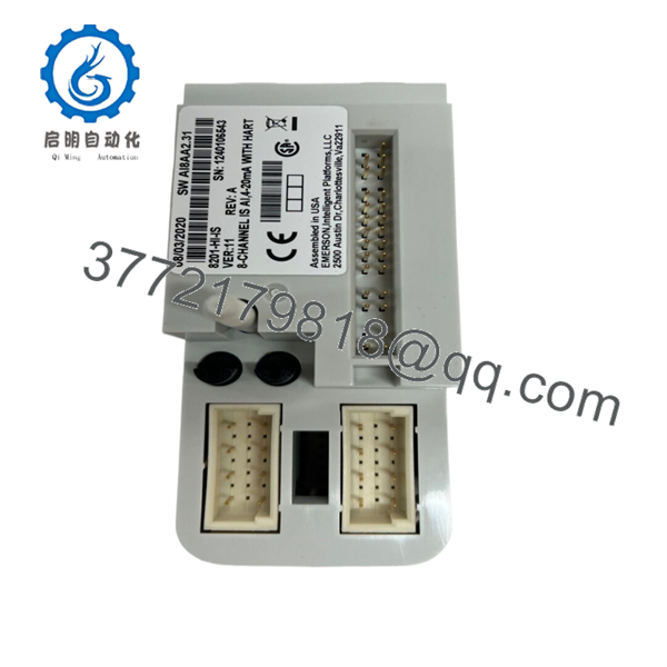
8201-HI-IS
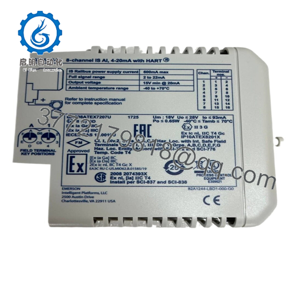
8201-HI-IS
Troubleshooting Quick Reference
| Symptom | Possible Cause | Relevance to this Part | Quick Check Method | Recommendation |
|---|---|---|---|---|
| All eight channels show 0 mA or invalid values | IS Railbus power loss, carrier problem, Bus Interface Module fault, configuration download issue | ⚠️ Medium | Check PAC8000 station diagnostics, carrier power, Railbus continuity, and status of adjacent intrinsically safe I/O modules. Confirm the module is configured and active in the engineering project. | Start with the carrier, Railbus, and station-level power. A total eight-channel failure is more likely common infrastructure than eight failed input circuits. |
| One channel reads below 0.5 mA | Open field cable, disconnected transmitter, failed transmitter, open terminal connection | ⚠️ Medium | Inspect the channel field terminal and transmitter head. With the loop isolated under the approved hazardous-area procedure, measure cable continuity and transmitter-loop current. | The module flags an open circuit below 0.5 mA. Check the transmitter and cable before replacing the 8201-HI-IS. |
| One channel reads above 21.5 mA | Short circuit, miswired transmitter, failed transmitter, incorrect test equipment connection | ⚠️ Medium | Review the module diagnostic state, inspect the terminal block, and check for conductor damage or water ingress. Verify the transmitter wiring polarity against its datasheet. | Treat a high-current indication as a field-loop issue first. Do not jumper or bypass an IS circuit without an approved procedure. |
| Input is fixed around 4 mA | Transmitter in fault or saturation mode, incorrect range configuration, blocked impulse line, process condition | ❌ Low | Connect a HART communicator through the approved interface and review device status. Compare local process condition with the transmitter’s configured low-alarm direction. | A stable 4 mA reading can be a valid process value or transmitter alarm output. Check HART diagnostics and process conditions before replacing the I/O module. |
| Input is fixed around 20 mA | Transmitter high alarm, over-range process condition, scaling mismatch, wiring or device issue | ❌ Low | Verify the raw input reading, transmitter HART status, process value, and engineering-unit scaling in the controller. | Diagnose the transmitter and process first. The analog input module only reports loop current; it does not create a 20 mA process alarm by itself. |
| HART device does not respond | HART disabled in module configuration, failed transmitter, wiring fault, incompatible connection method | ⚠️ Medium | Confirm HART communications are enabled for the channel. Verify a valid 4–20 mA loop current and use an approved HART communicator at the correct connection point. | Enable HART in the configuration and check the loop. Do not assume the module failed because a handheld communicator cannot connect. |
| HART variables update slowly | Normal HART scan timing, many HART channels active, controller polling configuration | ❌ Low | Compare the observed rate with the module’s stated HART response of up to 0.75 s per channel. Review channel polling and asset-management configuration. | This can be normal behavior. Use the 4–20 mA value for fast control input and HART for secondary variables, diagnostics, and configuration. |
| Reading is noisy or unstable | Cable shield error, ground loop, moisture, transmitter instability, nearby VFD or high-current wiring | ⚠️ Medium | Trend the raw mA value, inspect shield termination according to the approved IS installation drawing, and compare with a known-good loop calibrator where permitted. | Check transmitter power, cable condition, shielding, and grounding. Do not ground IS signal shields at both ends unless the engineered installation explicitly requires it. |
| Reading is consistently low at high process value | Excess cable resistance, loop-voltage margin too low, transmitter requires more voltage, poor terminal contact | ⚠️ Medium | At approximately 20 mA, measure transmitter terminal voltage using intrinsically safe approved test equipment and compare it with the required minimum. The module provides at least 15 V at 20 mA. | Calculate voltage drop across the cable and any approved IS hardware. Correct loop resistance or supply-margin issues before replacing the module. |
| Module does not seat or is rejected by the carrier | Wrong module keying, incompatible terminal, bent connector, wrong slot hardware | ⚠️ Medium | Verify Module Key Code A1. Confirm the installation uses the correct 8621-FT-IS standard or 8622-FT-IS loop-disconnect terminal assembly. Inspect connector contacts for damage. | Never force the module. Verify the carrier, terminal, keying, and approved hardware combination before energizing. |
| Multiple channels fail after field maintenance | Shared terminal disturbance, Railbus issue, configuration change, field wiring cross-connection | ⚠️ Medium | Compare affected channels against recent work permits and terminal changes. Review module diagnostics and confirm terminal blocks are fully latched. | Preserve the fault record and inspect common work areas first. A maintenance-induced multi-channel fault often comes from wiring or terminal handling, not card failure. |
❗ Intrinsic-safety warning: This is not an ordinary analog input card. Do not connect a standard loop calibrator, handheld meter, jumper, or temporary power source to the field terminals unless it is approved for the hazardous-area method and does not violate the loop’s entity parameters. The module’s output limits are Uo 28 V, Io 93 mA, and Po 0.65 W per channel.
❗ Terminal warning: Use the approved intrinsically safe field terminal. The standard 8621-FT-IS and loop-disconnect 8622-FT-IS terminals are identified for this module. A visually similar non-incendive or standard PAC8000 field terminal is not automatically acceptable for an IS circuit.
❗ Loop-voltage warning: At 20 mA, the module supplies at least 15 V to the transmitter. Long cable runs, high transmitter burden, corrosion at terminals, and unauthorized series devices can consume enough voltage to create a low or unstable measurement. Check voltage at the transmitter before calling the card bad.
❗ No channel isolation warning: The module isolates each channel from the Railbus, but it does not provide isolation between channels on the same module. Keep field wiring separated according to the approved design. A cross-connected return or shield mistake can affect more than one measurement.
Keep these checks in mind and you will save yourself 90% of typical rework time. If you need support, provide photos of the module and terminal type, channel diagnostics, hazardous-area drawing reference, transmitter model, measured loop current, HART status, and field-wiring test results.
Frequently Asked Questions (FAQ)
Q: What does the MTL 8201-HI-IS do?
A: The 8201-HI-IS reads eight 4–20 mA signals from two-wire field transmitters and brings those values into a PAC8000 I/O station. It includes intrinsically safe field circuits, internal loop power, HART pass-through, HART variable/status reporting, line-fault diagnostics, and programmable channel alarms.
Q: Is the 8201-HI-IS an analog input or analog output module?
A: It is an analog input module. It measures current from field transmitters; it does not command a valve positioner, I/P converter, or other output device. For intrinsically safe 4–20 mA output service, verify the correct 8202-HO-IS model instead.
Q: Can I connect standard 4–20 mA transmitters to this module?
A: Yes, when they are two-wire transmitters and the complete loop design meets the module’s intrinsic-safety and entity requirements. The module supports conventional 4–20 mA and HART-capable devices. Confirm transmitter approval, cable capacitance and inductance, field-terminal type, hazardous-area classification, and installation drawing before connection.
Q: Does the 8201-HI-IS power the field transmitter?
A: Yes. It has an internal transmitter power supply and provides at least 15 V to a transmitter at 20 mA. That voltage must still be sufficient after cable drop and any approved field-loop components. If the transmitter needs more than the available voltage, the loop may not reach full-scale current.
Q: Does every channel support HART?
A: Yes. The module provides HART pass-through and can report HART variables and status data. HART communication can be enabled or disabled per channel. Keep expectations realistic: the analog signal reaches Railbus availability in up to 33 ms, while HART response is specified at up to 0.75 seconds per channel.
Q: Can I hot-swap the 8201-HI-IS?
A: hardware supports hot-swap capability at the system level, but you must follow the site’s hazardous-area work authorization, process-safety requirements, carrier procedure, and control-system maintenance rules. Removing an analog input can create bad-quality process values, alarms, bypass requirements, or shutdown logic action. Do not treat hot-swap capability as permission to pull the card without a documented plan.
Q: Can I replace an 8201-HI-IS with a standard analog input module?
A: No, not where intrinsic safety is required. A general-purpose analog input module does not provide the same approved field-circuit energy limitation, entity parameters, IS terminal requirements, or hazardous-area installation basis. Replace like for like unless the complete loop is redesigned, reviewed, and approved by the responsible engineer.
Q: Why is New Surplus 8201-HI-IS stock less expensive than factory stock?
A: New Surplus normally means unused original inventory released from a plant spare-parts store, canceled project, distributor excess, or liquidation channel. The lower price may reflect older packaging, no current factory-channel support, or limited documentation—not necessarily poor condition. Request photos of the exact label, confirmation of unopened or unused condition, terminal-keying verification, incoming inspection results, HART/analog test details, written warranty terms, and actual lead time before purchase.



