
 WhatsApp: +86 16626708626
 Email:
  Phone: +86 16626708626
Description
Key Technical Specifications
| Parameter | Value |
|---|---|
| Manufacturer | MTL (Eaton Crouse-Hinds Series) |
| Model | F271-IS |
| Product Type | Intrinsically safe fieldbus Megablock |
| Series | F200-IS |
| Number of Spurs | 12 field device connections |
| Trunk Connection | 1 fieldbus trunk connection |
| Integrated Terminator | Yes |
| Supported Networks | Foundation Fieldbus H1, PROFIBUS PA |
| Hazardous Area Approval | ATEX / IECEx |
| Protection Concept | Ex ia intrinsic safety |
| Hazardous Area Classification | Ex ia IIC T4 Ga |
| Trunk Entity Parameters | Ui ≤ 24 V, Ii ≤ 250 mA, Pi ≤ 1.2 W |
| FISCO Parameters | Ui ≤ 17.5 V, Ii ≤ 380 mA, Pi ≤ 5.32 W |
| Maximum Spur Current | Approximately 40 mA |
| Power Consumption | Approximately 3.5 mA plus SpurGuard current when activated |
| Mounting Method | DIN rail mounting |
| Terminal Type | Pluggable screw terminal |
| Operating Temperature | -45 °C to +70 °C (verify installation conditions) |
| Application | Hazardous-area process instrumentation networks |
Product Introduction
The MTL F271-IS is an intrinsically safe 12-way Megablock fieldbus wiring hub designed for Foundation Fieldbus H1 and PROFIBUS PA installations in hazardous process environments. It provides connection points between a fieldbus trunk and multiple field devices while maintaining intrinsic safety separation requirements.
The module includes an internal terminator and supports Zone 1 hazardous-area applications with ATEX and IECEx approvals. When replacing an installed F271-IS, engineers should verify fieldbus segment design, trunk power calculation, device current requirements, and hazardous-area certification compatibility before commissioning.
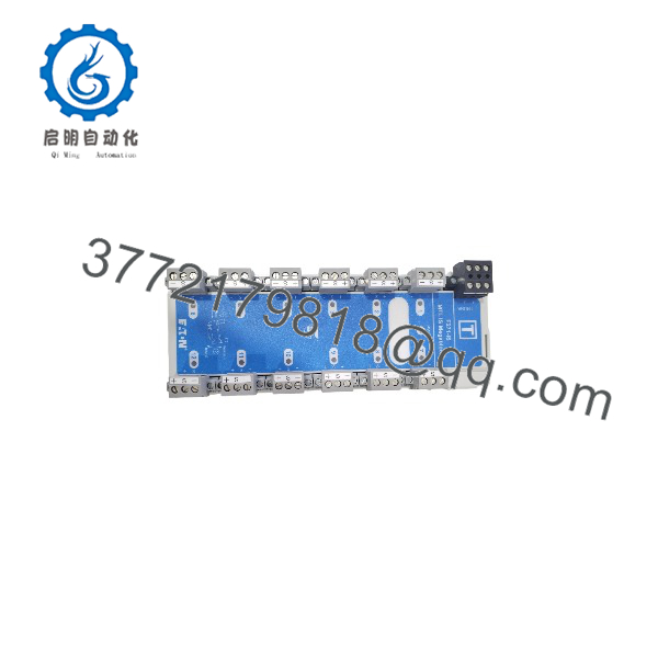
F271-IS
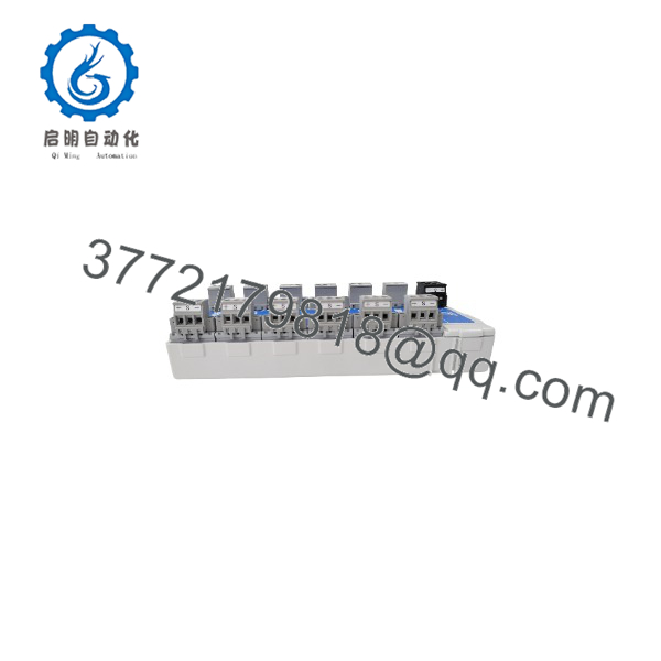
F271-IS
Installation & Configuration Guide
Stage 1: Pre-Installation Preparation (Approx. 15 minutes)
⚠️ Safety First
- Notify operations and obtain approval before opening the field junction cabinet.
- Confirm the process area is in a safe maintenance condition.
- Apply lockout/tagout procedures if the fieldbus segment remains energized.
- Verify hazardous-area work requirements before removing the device.
- Wait for stored electrical energy to discharge before handling terminals.
Tools Required
- ESD wrist strap
- Flat-head screwdriver
- Digital multimeter
- Wire labels
- Smartphone/camera for documentation
- Hazardous-area approved test equipment where required
Data Backup
Before removal:
- Record the existing F271-IS part number and terminal layout.
- Photograph:
- Trunk wiring
- Spur wiring
- Shield grounding
- DIN rail mounting position
- Document:
- Fieldbus segment address list
- Device current consumption
- Terminator location
- Cable shield grounding method
Stage 2: Removing the Old Module (Approx. 10 minutes)
- Remove cabinet or enclosure access cover.
- Label every trunk and spur cable before disconnecting.
- Disconnect terminal blocks carefully.
- Release the DIN rail locking mechanism.
- Remove the Megablock from the rail.
- Inspect:
- Terminal contacts
- DIN rail condition
- Shield grounding connection
- Cable insulation condition
⚠️ Note: Keep the original F271-IS until the replacement segment passes communication testing. Fieldbus wiring mistakes are easier to identify with the original unit available for comparison.
Stage 3: Installing the New Module (Approx. 15 minutes)
- Wear ESD protection before handling the replacement unit.
- Verify:
- Model: MTL F271-IS
- Function: 12-way IS Megablock with terminator
- Network: Foundation Fieldbus H1 or PROFIBUS PA
⚠️ Configuration Clone — Critical Step
- Reproduce the original wiring arrangement:
- Trunk + / –
- Spur + / –
- Cable shield connection
- Terminator configuration
- Mount the unit firmly on the DIN rail.
- Reconnect trunk wiring.
- Reconnect field device spurs.
- Verify terminal tightening.
Self-Checklist
- Cct model verified
- Trunk polarity checked
- Spur wiring matched
- Shield grounding confirmed
- DIN rail mounting secure
Stage 4: Power-On & Testing (Approx. 20 minutes)
Pre-Power Check
- Measure fieldbus segment voltage.
- Confirm no short circuit exists between trunk conductors.
- Verify shield connection follows site grounding practice.
Power-On Steps
- Energize the fieldbus segment.
- Check the green power LED.
- Verify no spur fault indicators are active.
- Connect the fieldbus diagnostic tool.
- Confirm:
- Segment voltage
- Device communication
- Device identification
- Signal quality
- Perform device-level communication tests.
⚠️ Troubleshooting Note
- No communication: Check trunk polarity, terminator placement, and segment power.
- Multiple devices offline: Check for trunk wiring faults or excessive segment current.
- One device offline: Check individual spur wiring and SpurGuard status.
Frequently Asked Questions (FAQ)
Can tTL be hot-swapped while the fieldbus is running?
No. Although fieldbus systems may support some live maintenance procedures, removing an intrinsic safety wiring hub without following hazardous-area procedures is not recommended. Verify site maintenance rules and the applicable MTL documentation before any energized work.
What is the main function of tTL ?
he provides a connection point between an intrinsically safe fieldbus trunk and up to 12 field devices. It is commonly installed in process automation applications using Foundation Fieldbus H1 or PROFIBUS PA networks.
Is tTL obsolete?
he is part of the MTL F200-IS Megablock product family. Availability depends on remaining industrial inventory. Many process plants maintain these modules as spare parts because replacing fieldbus infrastructure requires engineering changes and planned downtime.
Che replace other MTL Megablock models?
Not directlhe provides 12 spur connections with an internal terminator. Smaller models such as F251-IS or F253-IS have different channel counts and configurations. Confirm the required spur quantity and terminator arrangement before replacement.
Why is this module usually priced lower than current automation hardware?
Legacy fieldbus components are often sourced from surplus inventory or remaining production stock. Pricing depends on condition, availability, certification documentation, and testing records. New Original and tested refurbished units should be clearly identified before purchase.
What should I verify before ordering TL ?
Confirm:
- Exact l:
- Fieldbus type: Foundation Fieldbus H1 or PROFIBUS PA
- Required spur count
- Hazardous-area certification requirements
- Terminator configuration
- Terminal type
A visually similar fieldbus hub may not meet the same intrinsic safety requirements.
How should a sus be tested before installation?
A professional inspection should include:
- Verify OEM label and part number.
- Inspect terminals and housing condition.
- Check DIN rail mounting mechanism.
- Verify LED operation.
- Test fieldbus communication with a compatible segment.
- Record inspection results.
Test photos and inspection records should be retained for maintenance traceability.



