
 WhatsApp: +86 16626708626
 Email:
  Phone: +86 16626708626
Description
Key Technical Specifications
| Parameter | Value |
| Manufacturer | Eaton MTL Instruments |
| Part Number | F860-CA |
| System Compatibility | Accepts MTL F860 Fieldbus Power Supply Modules |
| Fieldbus Standard | FOUNDATION Fieldbus H1 (IEC 61158-2) |
| Host Power Inputs | Dual redundant 19.2 to 30.0 VDC screw terminals |
| Supported Topology | Redundant power conditioning per segment (N+1 or 1+1 configuration) |
| Segment Impedance | Integrated network terminators (selectable/switchable per segment) |
| Alarm Outputs | Volt-free relay contact terminals for power failure diagnostics |
| Mounting Style | Heavy-duty 35 mm DIN Rail or flat panel mounting |
| Operating Temperature | −40 °C to +70 °C (−40 °F to +158 °F) |
| Hazardous Area Approvals | Class I, Div 2 / Zone 2 (ATEX, IECEx, FM certified) |
Product Introduction & Supply Chain Strategy
The Eaton MTL F860-CA is a specialized carrier assembly engineered to house and power multiple F860 fieldbus power supply modules within FOUNDATION Fieldbus H1 architectures. Acting as the physical and electrical backplane, the carrier consolidates dual-redundant 24 VDC bulk power feeds, routes conditioned 28 VDC outputs to individual field segments, and incorporates built-in fieldbus terminators and diagnostic relay contacts.
Securing a New Surplus F860-CA carrier is a crucial risk-mitigation step for facilities reliant on centralized fieldbus networks. Refurbished backplane carriers present severe operational hazards: hairline trace cracks, fatigued terminal block contacts, or degraded busbar soldering can introduce intermittent power drops or high-frequency communication noise across multiple segments simultaneously. Investing in New Surplus guarantees factory-fresh backplane copper, robust screw terminals, and zero electrical stress—preventing multi-loop plant shutdowns and lowering overall Total Cost of Ownership (TCO).
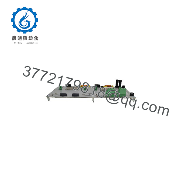
F860-CA
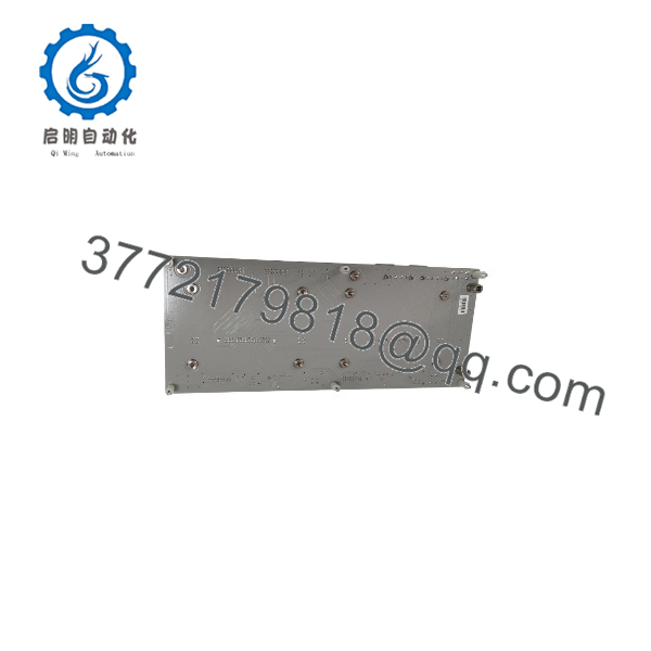
F860-CA
Installation & Configuration Guide
1.Stage 1: Pre-Installation (Prep & Safety):Prerequisite & Safety.
Execute Lock-Out/Tag-Out (LOTO) on primary and secondary 24 VDC bulk power supplies feeding the enclosure cabinet. Wear a grounded ESD wrist strap before handling the carrier backplane. Verify that the DIN rail mounting surface is grounded and free of debris.
2.Stage 2: Carrier Mounting & Terminal Prep:Mechanical Mounting.
Snap the F860-CA carrier firmly onto the 35 mm DIN rail, ensuring both metal mounting clips engage completely. Strip field segment and bulk power wiring to 7 mm. Connect the redundant 24 VDC power feeds to Host Power A and Host Power B terminals, torquing screws to 0.5 Nm.
3.Stage 3: Module Insertion & Termination Setup:Module Population.
Inspect the card edge connectors on the carrier slot for dust or debris. Align the power modules with the carrier guide channels and slide them in until the rear connectors seat fully into the backplane. Tighten the module retaining screws. Set the carrier jumper or DIP switches to enable the internal fieldbus segment terminator if the carrier serves as the segment end-point.
4.Stage 4: Power-On & Diagnostic Testing:Validation.
Energize both bulk 24 VDC power feeds. Confirm that the carrier power supply status LEDs illuminate green and that the common alarm relay contacts remain closed. Measure the DC output voltage at each fieldbus segment terminal block to confirm a steady 28 VDC supply, and run an oscilloscope or fieldbus diagnostic check to verify zero signal distortion.
Firmware/Software Versions & Upgrade Notes
- Hardware Nature: The -CA is a passive/active hardware backplane assembly and contains no programmable microcode or flash firmware.
- Module Matching: Designed exclusively for use with MTL series fieldbus power modules. Do not attempt to force non-F800 series modules onto the carrier edge connectors.
- Redundancy Management: The carrier backplane automatically manages power sharing between paired modules. If one module fails or is removed for maintenance, the carrier maintains continuous, uninterrupted power delivery to the fieldbus segment.
- Termination Logic: Ensure external fieldbus terminators are disabled if the -CA on-board terminators are activated, preventing double-termination network impedance drops.
Frequently Asked Questions (FAQ)
What is the key difference between the MTL and the ?
The MTL is the individual plug-in power supply module that conditions raw DC power. The is the carrier assembly (backplane card) that holds the modules, provides terminal blocks for field segment wiring, and routes dual 24 VDC bulk input power across the modules.
Why should our plant buy a New Surp carrier instead of a refurbished one?
Backplane carriers route high currents and high-frequency communication signals across multiple channels. Refurbished carriers often suffer from hidden solder joint fatigue, corroded screw terminals, or stress cracks in the printed circuit board that cause intermittent signal loss across several fieldbus segments. New Surplus guarantees factory-level board integrity and unblemished terminal contacts.
Can I swap out a failed power module on carrier while the segment is live?
Yes. When carrier is configured with redundant power modules per segment (1+1 or N+1 mode), you can hot-swap a faulty power module without de-energizing the carrier backplane or interrupting communication on the fieldbus segment.
Does carrier include built-in fieldbus segment terminators?
Yes. The carrier features integrated, selectable H1 segment terminators. These can be enabled or disabled via physical switches/jumpers on the carrier base, eliminating the need to install external DIN-rail mounted fieldbus terminators in the junction box.
What happens if one of the redundant 24 VDC bulk power inputs to the carrier fails?
incorporates diode-OR’d power input circuitry. If Host Power A fails, the carrier instantly draws full operating load from Host Power B without causing a voltage drop or ripple on the connected fieldbus segments. The alarm relay contact will open to notify the DCS of the input power loss.
What warranty and quality checks cover this carrier unit?
Every New Surplus carrier assembly undergoes comprehensive physical point inspection, backplane continuity verification, and ESD-safe protective packaging. Units are covered by a full 1-year replacement warranty.



