
 WhatsApp: +86 16626708626
 Email:
  Phone: +86 16626708626
Description
Key Technical Specifications
| Parameter | Specification Value |
| Manufacturer Model No. | GCB-101-02 |
| Product Category | Automatic Sliding Door Control Board |
| Control Architecture | Digital Microprocessor Logic |
| Input Voltage | 100 to 240 V AC (50/60 Hz system input) |
| Motor Drive Output | DC Motor Controller Output (PWM Speed Regulation) |
| Sensor Channels | Dual-channel activation & safety beam loop inputs |
| Auxiliary Interfaces | Electric lock output, battery backup header, mode selector switch switch contacts |
| Onboard Adjustments | Open/Close Speed, Hold-Open Timer, Slowdown Distance, Braking Force |
| Enclosure Type | Protective chassis-mounted circuit board assembly |
| Operating Temperature | -10 to +50 °C |
Product Introduction & Supply Chain Strategy
The NABCO GCB-101-02 is a high-precision microprocessor controller board engineered for NABCO commercial automatic sliding door operators. It manages full motion profile trajectories—including soft start, high-speed travel, safety slowdown, and position holding—while continuously processing inputs from activation sensors, safety beams, and auxiliary electric locks.
Securing the GCB-101-02 as New Surplus provides exceptional Total Cost of Ownership (TCO) optimization and keeps commercial building entrances safe and operational. Because a controller board failure halts automatic entrance operation, storing a genuine, unused surplus controller on-site allows facility engineers to execute an immediate replacement without paying full OEM header kit prices.
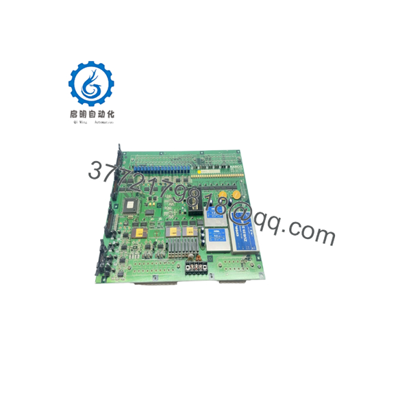
GCB-101-02
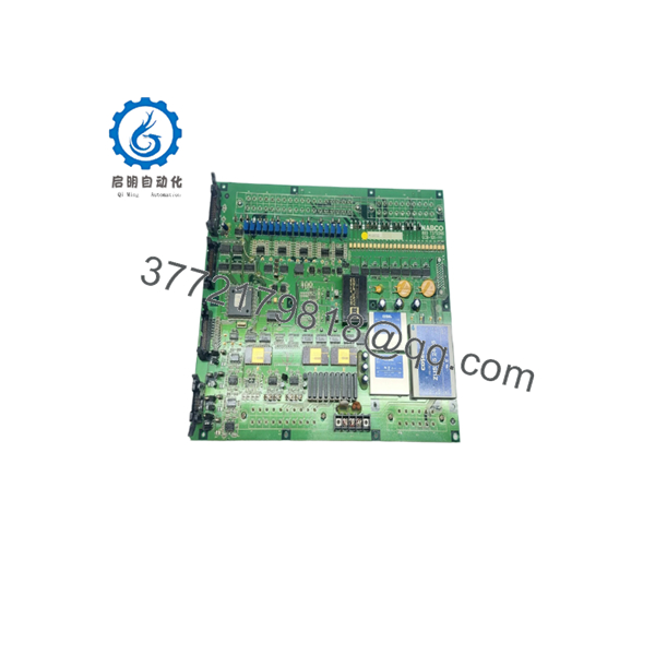
GCB-101-02
Installation & Configuration Guide
Stage 1: Pre-Installation (Prep & Safety)
- Execute Lock-Out/Tag-Out (LOTO) protocols on the main AC circuit breaker feeding the automatic door header box.
- Put on an ESD-grounded wrist strap before handling the replacement control board.
- Take high-resolution photos of all terminal block wire labels, DIP switch banks, and potentiometer trimmer settings on the old controller.
Stage 2: Removal
- Unplug the main power harness and DC motor connector from the GCB-101-02 board.
- Disconnect all auxiliary wiring harnesses, including activation sensors, safety beams, electric locks, and mode selector switches.
- Remove the mounting screws securing the controller chassis inside the header rail.
- Carefully lift out the old controller board assembly without straining adjacent wiring.
Stage 3: Installation (Clone & Seat)
- Mount the new NABCO GCB-101-02 board into the header channel and secure the mounting hardware.
- Replicate all potentiometer dial positions (Open/Close Speed, Hold-Open Time, Slowdown) and DIP switch configurations from the original board onto the new unit.
- Reattach the terminal block connectors, sensor wire leads, safety loops, and motor connections to their designated terminals.
Stage 4: Power-On & Testing
- Ensure the door pathway is completely clear of obstacles and manually slide the door panels to mid-travel position.
- Apply AC power. The controller will initiate its self-learning stroke-calibration cycle to determine physical end-stop positions.
- Walk through activation zones and safety beam paths to verify smooth opening profiles, soft deceleration, proper hold-open timing, and automatic obstruction reversal.
Firmware/Software Versions & Upgrade Notes
- Self-Learning Calibration: The GCB-101-02 features an automatic stroke-learning routine. Upon first power-up, the microprocessor detects door weight and travel distance to optimize braking curves.
- Potentiometer Adjustments: Fine-tuning of door motion profiles is performed using onboard analog trimmers. Use an insulated alignment tool to make minor calibration adjustments.
- Safety Sensor Logic: Ensure connected infrared safety sensors match the required contact logic (Normally Closed / Normally Open). Incorrect sensor wiring will prevent the controller from closing the door.
- Power Isolation Warning: Never connect or disconnect sensor harnesses or motor leads while AC power is live. Voltage transients can damage onboard microcontrollers and relay driver transistors.
Frequently Asked Questions (FAQ)
What is the financial benefit of choosing a New Surplus NABCO controller over a refurbished unit?
Commercial automatic doors endure thousands of daily cycles. Refurbished controller boards frequently suffer from degraded capacitors and worn relay contacts that fail prematurely under heavy foot-traffic loads. Our New Surplus inventory consists of 100% genuine, unused OEM controllers from reserve facility stock. You receive factory-grade reliability and full service life at a substantially lower price than purchasing a brand-new door header assembly.
Is this NABCO unit guaranteed to be brand new and genuine?
Yes. Every supplied is certified Original New Surplus. They feature zero operational field cycles, clean connector pins, pristine PCB traces, and original manufacturer markings. Units are inspected exclusively under ESD-safe warehouse conditions.
Why is keeping a spare door controller on-site critical for facility management?
A failed door controller causes immediate security vulnerabilities, energy loss, and ADA compliance issues. Storing a pre-tested spare in facility stock enables building maintenance teams to complete a hardware swap in under 30 minutes, keeping your main entrance secure and fully operational.
Can I hot-swap the controller while the door header is energized?
No. Always isolate main AC power before making terminal connections or replacing the controller. Hot-plugging power harnesses or motor leads can cause electrical arcing, blow onboard fuses, or damage sensitive microprocessor inputs.



