
 WhatsApp: +86 16626708626
 Email:
  Phone: +86 16626708626
Description
Key Technical Specifications
- Manufacturer: NABCO
- Model: MC-103-02Z
- Product Type: PCB Card
- Part Number: 885 72739840
- Application: Marine engine control system
- System Category: Marine automation / engine control
- Board Function: Control-system printed circuit board
- Mounting: System-specific PCB installation
- Supply Voltage: Not publicly verified; confirm against the vessel’s NABCO documentation
- Communication Interface: Not publicly verified for this specific revision
- Operating Temperature: Not publicly verified
- Dimensions / Weight: Not publicly verified
Publicly available supplier records identify the NABCO MC-103-02Z as a PCB for an engine control system and associate it with part number 885 72739840.
Important identification note: Some secondary listings associate the same 885 72739840 number with other NABCO board designations. Do not order from the numeric part number alone. Compare the board label, revision marking, connector layout, and installed system documentation before replacement.
Product Introduction
The NABCO MC-103-02Z is a NABCO printed circuit board used in marine engine control equipment. Supplier and inventory records identify it specifically as an engine-control-system PCB, with part number 885 72739840.
This board is primarily relevant when maintaining an existing NABCO marine control installation where the original PCB must be replaced without redesigning the control system. Because detailed OEM electrical specifications are not readily available in the public sources reviewed, verify the board revision, connectors, installed system, and electrical requirements before installation.
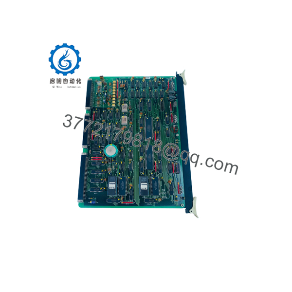
MC-103-02Z
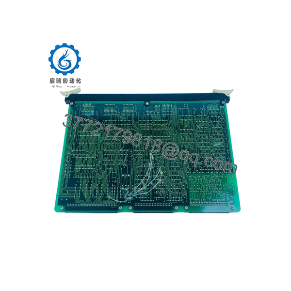
MC-103-02Z
Installation & Configuration Guide
Stage 1: Pre-Installation Preparation — Approximately 10 Minutes
⚠️ Safety First: Coordinate the maintenance window with vessel operations. Put the affected engine/control system into the manufacturer’s specified safe state. Apply lockout/tagout procedures where applicable and isolate power before removing the PCB.
Tools Required
- ESD wrist strap and grounded ESD work surface
- Insulated screwdriver set appropriate for the enclosure
- Digital multimeter
- Wire and connector labels
- Smartphone or camera for documenting the existing installation
- NABCO system drawings or vessel-specific maintenance documentation
Data Backup and Identification
- Record the complete designation from the existing PCB.
- Photograph the board label, revision markings, connectors, terminal positions, and mounting arrangement.
- Record any jumper, switch, or configuration settings.
- Photograph the wiring before disconnecting anything.
- Confirm that the replacement is NABCO MC-103-02Z and compare its physical identification with the removed board.
- Retain the original board until commissioning is complete.
⚠️ Do not assume that a similar-looking NABCO PCB is interchangeable. Public listings show multiple MC-series boards with closely related designations, so physical and documentation-based identification matters.
Stage 2: Removing the Old Module — Approximately 5 Minutes
- Confirm that the control system is isolated and electrically safe.
- Attach the ESD wrist strap before handling the PCB.
- Remove the required enclosure cover or access panel.
- Photograph all connectors before removal.
- Label connectors if their positions could be confused.
- Disconnect connectors without pulling on individual wires.
- Release the PCB mounting hardware or retaining mechanism.
- Remove the board straight and avoid flexing the PCB or contacting exposed circuitry.
- Inspect the connector sockets, pins, mounting points, and surrounding wiring for corrosion, contamination, or mechanical damage.
⚠️ Keep the removed MC-103-02Z available for comparison. Do not discard it until the replacement has completed functional testing.
Stage 3: Installing the Replacement PCB — Approximately 5–10 Minutes
- Verify the replacement label against the removed board.
- Confirm the model designation MC-103-02Z.
- Confirm the applicable part number and revision markings against the vessel documentation.
- Compare connector locations and board orientation.
- Install the PCB without forcing any connector or mounting point.
- Secure the PCB using the original mounting hardware.
- Reconnect each connector according to the photographs and wiring documentation.
- Check that every connector is fully seated.
- Verify that no wire is trapped under the PCB or enclosure cover.
Configuration Clone — Critical Check
If the original board contains configurable jumpers, switches, links, or removable settings, reproduce the documented configuration exactly.
Do not assume factory-default settings are suitable for the vessel.
Pre-Power Checklist
- Correct MC-103-02Z designation verified
- Part number verified against system documentation
- PCB orientation correct
- Connectors fully seated
- Wiring matches photographs
- Mounting hardware secured
- No visible PCB or connector damage
- ESD precautions maintained
Stage 4: Power-On and Functional Testing — Approximately 10 Minutes
- Perform a visual inspection before energizing the equipment.
- Verify that no conductive object, loose wire, or tool remains inside the enclosure.
- Check the applicable supply circuit according to the NABCO system documentation.
- Restore power following the vessel’s approved startup procedure.
- Observe the PCB and associated system indicators.
- Check for abnormal alarms or fault indications.
- Verify communication with the associated engine-control equipment where applicable.
- Perform the manufacturer’s specified engine-control functional checks.
- Confirm that commanded functions and feedback signals behave normally.
- Record the replacement date, board identification, and test results in the maintenance record.
⚠️ Do not infer a fault from an LED pattern without the applicable NABCO documentation. The public sources reviewed identify the MC-103-02Z as an engine-control PCB but do not provide a reliable LED diagnostic table for this exact revision.
Frequently Asked Questions (FAQ)
Can the NABCO MC-103-02Z be hot-swapped?
Do not assume that it can. Publicly available documentation reviewed for this specific part does not establish a hot-swap procedure. Isolate power and follow the vessel’s NABCO maintenance procedure unless the OEM documentation explicitly permits energized replacement.
What is the part number for NABCO MC-103-02Z?
Available supplier records identify 885 72739840 as the associated part number.
However, there are conflicting secondary listings involving closely related NABCO board designations. For procurement, verify both the MC-103-02Z model marking and the physical board label rather than relying on a database entry alone.
What does the MC-103-02Z do?
Available supplier information identifies it as a PCB used in a NABCO engine control system. Detailed functional circuit descriptions are not publicly documented in the sources reviewed, so its exact I/O or control role should be confirmed from the vessel-specific NABCO drawings before commissioning.
Is NABCO MC-103-02Z an obsolete part?
The part appears primarily through specialist marine automation and surplus-spares inventories rather than current mainstream industrial automation catalogs. That suggests procurement may depend on remaining spare inventory. However, the sources reviewed do not provide an official NABCO end-of-life notice, so it would be inaccurate to state formal obsolescence without OEM confirmation.
Is a used MC-103-02Z suitable as a replacement?
It can be considered only after appropriate inspection and functional testing. A used marine PCB may have been exposed to vibration, humidity, salt contamination, thermal cycling, or previous electrical faults. Check connectors, PCB surfaces, corrosion, rework marks, and component condition before installation.
Why should I verify the board revision before ordering?
Because secondary inventory records are not completely consistent. The MC-103-02Z is associated with 885 72739840 in multiple listings, while another listing associates that same number with a different MC-series designation.
For a marine control system, that is enough reason to request a clear photograph of the actual nameplate and PCB markings before approving a replacement.
Can you supply a New Original or Refurbished MC-103-02Z?
Availability and condition vary by inventory. Public market listings currently show both used and new/open-box examples of the MC-103-02Z.
For procurement, specify the required condition—New Original / New Surplus or Refurbished / Tested—and request confirmation of the exact model marking, part number, photographs, and test status before purchase.



