
 WhatsApp: +86 16626708626
 Email:
  Phone: +86 16626708626
Description
Key Technical Specifications
| Parameter | Specification |
| Model Number | MC-603-07I |
| Part Series | 885 Series (Sub-assembly family 885 72739837) |
| Manufacturer | NABCO (Nabtesco Corporation) |
| Primary Application | Marine main engine remote control & propulsion safety systems |
| Circuit Function | Output relay driving, interlock logic processing, and signal routing |
| Supply Voltage | 24 V DC nominal (±10%) |
| Input Signals | Opto-isolated digital inputs from bridge and ECR consoles |
| Output Contacts | High-reliability relay outputs and solid-state driver channels |
| Operating Temperature | -10°C to +70°C (14°F to 158°F) |
| Environmental Protection | Conformal coating against moisture, salt fog, and marine vibration |
| Weight | 0.47 kg (1.04 lbs) |
Product Introduction & Supply Chain Strategy
The NABCO MC-603-07I is a specialized command logic and output driver PCB module engineered for NABCO main engine remote control consoles. Positioned within the central control rack, it processes directional commands, interlock signals, and start/stop outputs between the bridge telegraph, ECR control panel, and main engine actuators.
Carrying a genuine New Surplus MC-603-07I card in critical buffer stock is a key risk management measure for fleet operators. Failure of an engine remote control logic module locks down propulsion signaling, risking port detentions and costly off-hire hours. Securing unused original inventory guarantees fresh capacitors and zero contact wear, bypassing long OEM lead times while avoiding the high failure rates associated with second-hand units.
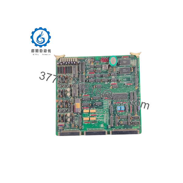
MC-603-07I 885
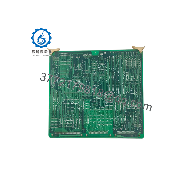
MC-603-07I 885
Installation & Configuration Guide
Stage 1: Pre-Installation (Prep & Safety)
- Power Isolation: De-energize the main 24V DC power feed to the marine engine control cabinet. Confirm zero voltage with a digital multimeter before touching components.
- ESD Protection: Attach a grounded ESD wrist strap before handling the replacement card.
- Record Configuration: Photograph and document all onboard DIP switch settings, jumper positions, and connector wiring labels on the original unit.
Stage 2: Removal
- Disconnect all edge-connector terminal blocks and wire harness plugs without pulling on individual lead wires.
- Unfasten the retaining screws securing the board to the rack chassis or mounting standoffs.
- Carefully slide the PCB straight out to prevent bending or damaging the rear backplane pin array.
Stage 3: Installation (Clone & Seat)
- Match and duplicate every DIP switch bank and jumper pin configuration from the old card onto the replacement MC-603-07I.
- Align the board with the guide rails and press it firmly into place to seat the backplane connector completely.
- Fasten mounting screws to 0.8 N·m to guard against continuous engine room vibration.
Stage 4: Power-On & Testing
- Re-apply 24V DC system power. Confirm the main status LED illuminates solid green without fault indications.
- Conduct a stationary control sequence test from the ECR desk to verify relay actuation and command handshakes.
- Validate interlock safety logic before returning the propulsion control system to active service.
Firmware/Software Versions & Upgrade Notes
- Hardware-Driven Architecture: The MC-603-07I operates using discrete logic ICs and factory-flashed EPROMs. Field software downloads or laptop flashing tools are not required.
- Sub-Revision Compatibility: The “07I” suffix designates a specific hardware sub-revision within the NABCO MC-603 PCB family. While physical board footprints are shared across the MC-603 series, verify terminal pinouts when cross-substituting variants like
01A,02F, or08Eto ensure output relay logic matches your cabinet wiring. - Configuration Warning: Always match jumper configurations to the original board layout. Incorrect jumper placement can alter relay output timing and lead to interlock fault loops during engine starting.
Frequently Asked Questions (FAQ)
Is this NABCO MC-603-07I 885 module new or refurbished?
This product is a Brand New Surplus unit. It is not used, not pulled from a decommissioned vessel, and not refurbished. All modules undergo quality inspection to ensure OEM-level reliability.
Why buy New Surplus over a refurbished PCB for marine applications?
Refurbished PCB modules often contain aged electrolytic capacitors and microscopic solder fractures caused by continuous vessel vibration. A failure in the main engine logic control during harbor maneuvering can result in severe marine safety risks. New Surplus provides full 10–15 year component longevity and absolute reliability at a fraction of OEM list price.
Does replacing the MC-603-07I require software programming?
No laptop software or programming tools are needed. The module functions purely on hardware logic and onboard DIP switch/jumper settings.
Are all NABCO MC-603 series boards interchangeable?
The core frame and power rail connectors are similar across the MC-603 platform, but sub-revisions (such as MC-603-01A or MC-603-02F feature varying relay logic matrixes. Confirm your part number or electrical schematic before cross-substituting.
What warranty is provided with this New Surplus PCB?
Every NABCO MC-603-07I board supplied from our inventory comes backed by a 1-year functional replacement warranty.



