
 WhatsApp: +86 16626708626
 Email:
  Phone: +86 16626708626
Description
3. Key Technical Specifications
| Parameter | Value |
|---|---|
| Number of Channels | 32 digital outputs |
| Organization | 8 optically isolated banks of 4 channels each |
| Output Type | Open-collector with 4.7 kΩ pull-ups |
| Compatibility | Most TTL and CMOS logic |
| Isolation | Port-to-port and port-to-ground: 250–300 Vrms working, 1,900 Vrms breakdown |
| Supply Voltage (Vcc per bank) | +5 V ±0.5 V (user-supplied) |
| Supply Current (per bank) | 60 mA typical, 80 mA maximum |
| Output Current (low) | 15 mA maximum |
| Logic Low Voltage | 0.4 V typical @ 12 mA |
| Propagation Delay (parallel) | 100 ns |
| Common-Mode Transient Rejection | 500 V/µs typical |
| Front Connector | 48-pin DIN C male |
| Rear Connector | 50-pin male ribbon-cable |
| Dimensions | 1.2 × 6.8 × 8.0 in. |
| Operating Temperature | 0 °C to 50 °C |
4. Product Introduction
The National Instruments SCXI-1163 is a 32-channel optically isolated digital output module for the SCXI platform. The channels are arranged in eight isolated banks of four open-collector outputs each, providing galvanic isolation between banks and from the chassis ground.
Engineers use the SCXI-1163 when field digital signals must be driven while isolating the host DAQ system from ground loops and potentially damaging voltages. Each bank requires its own external +5 V supply and ground. The module operates in multiplexed mode through the SCXI chassis or in parallel mode when cabled directly to a DIO device. As an obsolete SCXI module, remaining New Surplus units continue to support legacy SCXI-based test and control systems.
5. Installation & Configuration Guide
Stage 1: Pre-Installation Preparation (≈10 min)
⚠️ Safety First: Power down the SCXI chassis and any connected DAQ devices. Disconnect all field wiring.
Tools Required: ESD wrist strap, SCXI chassis screwdriver or thumbscrews, multimeter, appropriate terminal block or cable (e.g., SCXI-1326 or custom), smartphone for photos of existing wiring and jumpers.
Data Backup: Record the chassis slot number, any jumper settings, and the software configuration (NI-DAQmx or Traditional NI-DAQ) for this module.
Stage 2: Removing the Old Module (≈5–10 min)
- Confirm the chassis is powered off.
- Label and disconnect the front-panel connector or terminal block.
- Release the module from the SCXI chassis and slide it straight out.
- Inspect the chassis backplane connectors and the module edge connector for damage or contamination.
⚠️ Retain the old module until the replacement has been fully verified in the system.
Stage 3: Installing the New Module (≈10–15 min)
- Verify the exact model marking SCXI-1163 (Part Number typically 776572-63).
- Set any required jumpers according to the application (refer to the user manual for address or mode settings).
- Insert the module firmly into the correct SCXI chassis slot until it seats fully. Secure with the chassis fasteners.
- Connect the front-panel wiring or terminal block. Supply a separate +5 V and ground to each bank that will be used.
Self-Checklist: [ ] Model confirmed [ ] Jumpers set correctly [ ] Module fully seated [ ] Vcc and GND connected to each active bank [ ] Field wiring polarity verified.
Stage 4: Power-On & Testing (≈15 min)
Pre-Power Check: Confirm correct +5 V supply polarity and voltage on each bank. Verify no short circuits on the output lines.
- Power up the SCXI chassis and host computer.
- In Measurement & Automation Explorer (MAX) or the appropriate driver, detect the SCXI-1163 and verify it appears in the correct slot.
- Write test patterns to individual banks and confirm the corresponding open-collector outputs switch correctly with a multimeter or logic probe.
- Verify isolation between banks if required by the application.
- Run a short application test under normal load conditions.
⚠️ Troubleshooting Note: Outputs that do not switch usually indicate missing or incorrect Vcc/GND on that bank. Isolation failures or communication errors are most often caused by incorrect chassis address jumpers or a damaged rear connector. Never exceed 5.5 V on any bank Vcc.
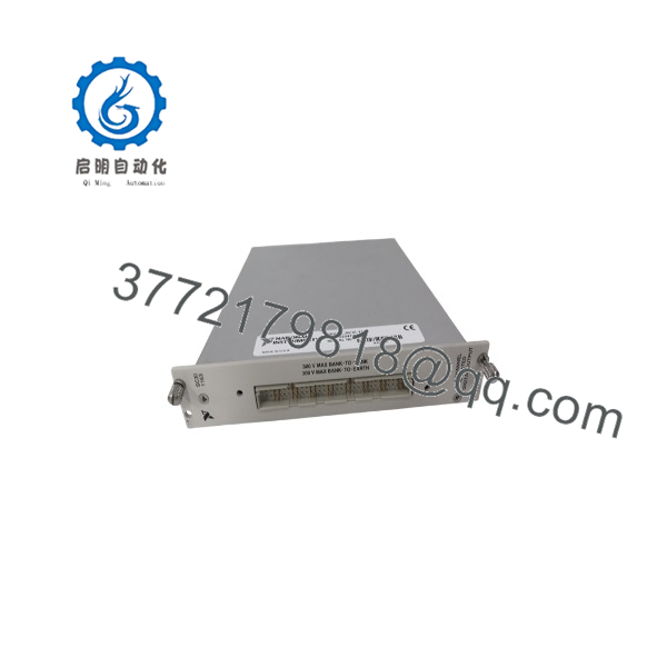
SCXI-1163
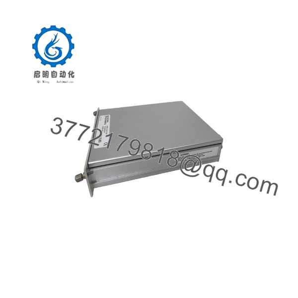
SCXI-1163
6. Frequently Asked Questions (FAQ)
Q: Can the SCXI-1163 be hot-swapped under power?
No. Always power down the SCXI chassis before inserting or removing modules. Hot-swapping can damage the backplane or the module.
Q: Is this model obsolete, and is the stock genuinely new?
Yes, the SCXI-1163 is an obsolete National Instruments module. Available units are New Original (new surplus) stock that has been functionally verified. Quantities are limited.
Q: What is the direct replacement if stock is exhausted?
Modern NI CompactDAQ or CompactRIO digital output modules (or the SCXI-1163R solid-state relay version if higher voltage switching is needed) can provide similar isolation and channel counts. Confirm software compatibility and physical form factor before substitution.
Q: Will I lose configuration when I replace the module?
Configuration is stored in the host software and chassis settings, not in the module itself. Re-create the device in MAX and reload any saved scale or channel configurations.
Q: Why is the price lower than original NI list price?
These are New Surplus units from secondary-market inventory. They provide the same form, fit, and function as original production modules and are fully tested, but they are no longer current-production catalog items.
Q: Does each bank need its own power supply?
Yes. Each of the eight banks requires its own external +5 V (±0.5 V) supply and ground reference. Without Vcc and GND on a bank, the four outputs in that bank will not function.
Q: What is the difference between and SCXI-1163R?
The provides open-collector TTL/CMOS digital outputs. The SCXI-1163R uses solid-state relays (Form A) capable of switching up to 240 VAC/VDC at 200 mA.



