
 WhatsApp: +86 16626708626
 Email:
  Phone: +86 16626708626
Description
Key Technical Specifications
| Parameter | Specification |
| Interface Compatibility | IEEE 488.1, IEEE 488.2, and HS488 Protocol |
| Max Transfer Rate | Up to 1.1 MB/s (Standard IEEE 488.1) / Up to 2.8 MB/s (HS488) |
| Maximum Extension Distance | Up to 1 km (Fiber Optic T7 cable) / Up to 2 km (GPIB-140A/2) |
| Device Capacity Expansion | Expands standard 15-device limit up to 26 GPIB instruments |
| Transmission Medium | Fiber-Optic Cable (provides complete electrical isolation) |
| Error Checking | Built-in buffered hardware error checking protocol |
| AC Power Inputs | Region-specific power options (100V, 120V, 220V, 240V AC, 50/60 Hz) |
| Form Factor | Compact external tabletop / benchtop enclosure |
Product Introduction & Application Context
The National Instruments GPIB-140A is a specialized fiber-optic GPIB bus extender engineered to overcome the strict physical distance and loading limitations of the standard IEEE 488 bus. Under standard GPIB rules, total cable length is restricted to 20 meters and maximum device count is limited to 15 instruments. Operating in matched pairs, two GPIB-140A units transparently bridge distances up to 1 kilometer using fiber-optic cabling while expanding device capacity up to 26 instruments.
Because fiber-optic cables transmit light rather than electrical currents, the GPIB-140A provides total galvanic isolation between instrument clusters and the main control workstation. This makes it an ideal solution for test environments subject to severe ground loops, high electromagnetic interference (EMI), high-voltage isolation requirements, or physical separation across facility buildings.

GPIB-140A
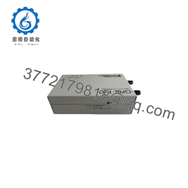
GPIB-140A
Installation & Configuration Guide
1.Physical Placement & Cabling:Position extenders near local and remote GPIB device clusters.
Place one GPIB-140A near the host computer/controller and the second unit near the remote test instruments. Connect the fiber-optic link cable (TX to RX, RX to TX) between the two extenders.
2.GPIB Bus Connection:Connect standard GPIB cables to local and remote buses.
Attach a standard IEEE 488 GPIB cable from the host controller to the local GPIB-140A. Attach a second GPIB cable from the remote to the remote cluster of test instruments.
3.Power Supply Verification:Select region-correct AC power and switch on units.
Verify the voltage setting matches local AC power (100V, 120V, or 220/240V AC). Plug in AC power cords to both units and toggle the rear power switches.
4.Link Diagnostics & System Integration:Verify LED indicators and test communication.
Check front panel LEDs: Power should be solid GREEN, and Link status should confirm established optical communication. Run NI-MAX (Measurement & Automation Explorer) software to scan for remote GPIB device addresses.
Software & Application Transparency
- Zero Software Modification: The operates transparently at the physical layer. Existing test programs written in LabVIEW, C/C++, or Python using NI-VISA / NI-488.2 drivers require no code modifications.
- HS488 High-Speed Support: Supports NI’s high-speed HS488 protocol, allowing data transfer speeds up to 2.8 MB/s over fiber optic links without timing handshake errors.
- Device Address Handling: Correctly forwards IEEE 488 address scanning routines (such as Find All Listeners), maintaining full instrument discovery capabilities.
Frequently Asked Questions (FAQ)
Q: Do I need two units to establish a extended bus link?
A: Yes. extenders must be used in matching pairs—one unit at the host controller end and one unit at the remote instrument cluster.
Q: What is the main difference between the and /2?
A: The standard supports fiber optic extension up to 1 kilometer, while the /2 variant supports distances up to 2 kilometers.
Q: Does the fiber optic connection provide electrical isolation?
A: Yes. Fiber optic transmission eliminates electrical ground loops and prevents high-voltage transients from traveling between the remote test station and the control computer.
Q: What happens if the fiber optic cable is accidentally disconnected during operation?
A: Built-in hardware error checking detects link loss, halting transfer attempts safely to prevent data corruption until optical link integrity is restored.



