
 WhatsApp: +86 16626708626
 Email:
 Phone: +86 16626708626
Description
Key Technical Specifications
NI specifies typical performance at 25 °C unless otherwise noted. Analog output update rates depend on the host system.
| Parameter | Value |
|---|---|
| Analog Inputs | 4 pseudodifferential channels; simultaneous sampling |
| ADC Resolution | 12 bits; dedicated ADC per channel |
| Input Sampling Rate | 1 kS/s to 5 MS/s per channel |
| Analog Input Ranges | ±0.2 V, ±0.5 V, ±1 V, ±2 V, ±5 V, ±10 V, ±20 V, ±42 V |
| Input Coupling and Impedance | AC or DC; 1 MΩ in parallel with 100 pF between AI+ and AI−, powered on |
| Analog Outputs | 2 channels; 16-bit resolution; ±10 V range; DC coupled |
| Maximum AO Update Rate | 4 MS/s with one channel; 2.5 MS/s per channel with two channels; system dependent |
| Digital I/O | 8 TTL/CMOS-compatible input/output lines |
| Counter/Timers | 2 channels; 24-bit resolution; maximum source frequency: 20 MHz |
| Bus and Signal Connector | Conventional PCI; 68-pin male SCSI-II-type I/O connector |
| Power and Dimensions | +5 V DC ±5%, 2.5 A; 312 × 106 mm, excluding connectors |
| Operating Environment and Calibration | 0 to 45 °C; 5–90% RH, noncondensing; 15-minute warm-up; recommended 1-year calibration interval |
Specifications derive from NI’s PCI-6110/6111 specification sheet and PCI-6110 product information.
❗ Warning: The ±42 V range does not permit arbitrary common-mode voltage. AI− must remain within ±11 V of ground on all ranges. AI+ must remain within ±11 V on ranges through ±10 V, or within ±42 V on the ±20 V and ±42 V ranges. The card is rated for Installation Category I—not direct mains measurements.
Product Introduction
The NI PCI-6110 is an S Series multifunction DAQ card for high-speed, simultaneous measurements in PCI-based test systems. Four dedicated 12-bit ADCs acquire signals at up to 5 MS/s per channel, supporting transient capture and synchronized stimulus/response testing.
Two 16-bit analog outputs, eight digital I/O lines, and two 24-bit counters combine acquisition, waveform generation, and timing on one board. Choose it when simultaneous sampling and existing PCI-system compatibility matter; verify full-length chassis clearance before ordering.
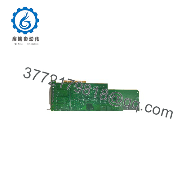
PCI-6110
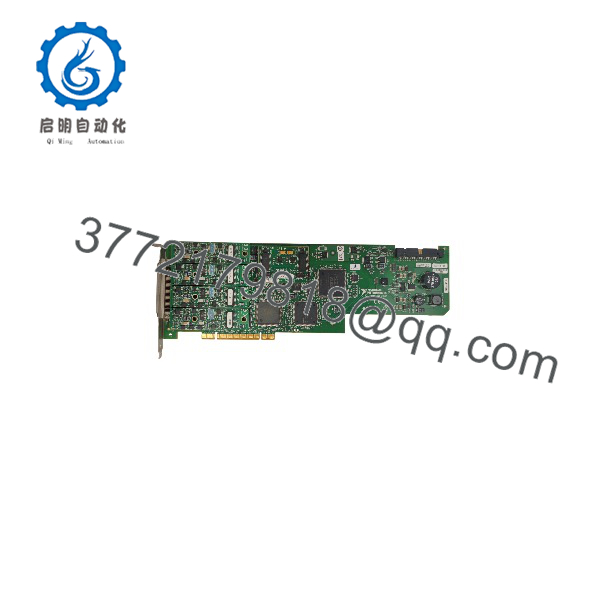
PCI-6110
Troubleshooting Quick Reference
| Symptom | Possible Cause | Relevance to this Part | Quick Check Method | Recommendation |
|---|---|---|---|---|
| Card does not appear in NI MAX | Driver incompatibility, incomplete seating, or host PCI problem | Possible hardware issue; not established | Check OS hardware enumeration; verify the installed driver supports PCI-6110 and the OS; power down before inspecting seating | Confirm host and software compatibility before replacing |
| All analog inputs read flat | Wrong channel selection, missing signal, or task waiting for a trigger | Configuration and wiring first | Select an internal sample clock and immediate start; apply a known 1 kHz, 1 V peak-to-peak signal to AI0+/AI0− within common-mode limits | Repeat with the same source and cable on each channel |
| One channel clips or reads incorrectly | Wrong range, common-mode violation, cable fault, or damaged input | Higher hardware suspicion only after isolation | Set the ±2 V range; apply the same known signal to all channels; measure AI+ and AI− relative to AI GND | Correct grounding and range before condemning the input |
| DC level disappears or slow signals droop | AC coupling selected | Expected configuration behavior | Read the channel coupling setting; repeat with DC coupling and a known DC source | Use DC coupling when the measurement requires DC content |
| Acquisition fails at high rates | Host transfer limits, software buffering, or PCI contention | System-level issue possible | Test one channel first, then four; log the exact error and reduce the sampling rate | Check buffering, data handling, and bus loading before replacement |
| AO waveform amplitude falls under load | Excessive load or output impedance effects | Output-stage limitation possible | Disconnect the load; measure AO relative to AO GND using a high-impedance instrument | Check load requirements; NI specifies 50 Ω output impedance and ±5 mA minimum drive capability |
| Digital I/O does not switch external equipment | TTL/CMOS versus industrial-voltage mismatch | Interface limitation, not necessarily failure | Verify line direction and measure the logic level relative to D GND | Use appropriate interface circuitry; do not connect 24 V directly to digital lines |
Checks reference NI’s input configuration, software setup, signal connections, output limits, and digital logic specifications. They do not establish failure frequency.
If the fault remains, contact technical support with actual-unit photos, terminal-block and cable identifiers, OS and driver versions, task settings, exact error codes, and captured measurements.
Frequently Asked Questions (FAQ)
Can I hot-swap the PCI-6110?
No. NI’s installation procedure requires powering off and unplugging the computer before inserting the card. Remove power from signal lines before connecting or disconnecting them, and use grounded ESD protection.
Check mechanical clearance before removal or replacement. The board measures 312 × 106 mm without connectors, and NI specifically requires a chassis that accommodates full-length PCI modules. A short PCI slot area or obstructing drive cage can stop the installation even when the electrical interface is correct.
Is the PCI-6110 a direct replacement for the PCI-6111 or PCI-4462?
Do not treat either as an automatic substitute.
- PCI-6111: NI specifies two analog input channels, versus four on the PCI-6110. That difference alone prevents equivalent replacement in a four-channel application.
- PCI-4462: NI specifies four 24-bit sound-and-vibration inputs at up to 204.8 kS/s per channel. The PCI-6110 instead provides four 12-bit inputs at up to 5 MS/s per channel, plus analog outputs, digital I/O, and counters. These are different acquisition architectures and capabilities.
For a PCI-6110-to-PCI-6110 replacement, verify the actual board label, supported driver/OS combination, cable pinout, terminal block, trigger routing, and application settings before purchasing.
Will my program and configuration survive a card replacement?
The PCI-6110 is a host-controlled DAQ card, not a PLC CPU storing the machine’s application program. NI documents configuration and operation through host software. Back up the application, driver installer, device configuration, scaling, channel assignments, and trigger settings before removal.
Record the installed software versions instead of assuming the newest driver will support an older application. NI’s documentation spans Traditional NI-DAQ and NI-DAQmx terminology, so confirm which API the existing program actually uses. No firmware revision was supplied; a specific firmware-compatibility claim would be unsupported.
There are no DIP switches, jumpers, or potentiometers to copy. NI explicitly describes this device as switchless and jumperless. Capture software settings—not an imaginary node-address switch pattern.
Can I reuse my existing 68-pin cable and terminal block?
Only after checking the exact accessory model and wiring diagram. A matching connector shell does not establish compatible signal assignments.
The card uses a 68-pin male SCSI-II-type signal connector. Verify AI+/AI− pairs, analog grounds, AO connections, digital lines, and PFI signals against the PCI-6110 documentation. NI also documents naming differences between Traditional NI-DAQ and NI-DAQmx. Do not wire from memory or apply a newer terminal name without checking its equivalent.
For custom wiring, NI recommends shielded twisted pairs for analog inputs, separating analog and digital wiring, and connecting each analog pair’s shield to the source ground reference. Follow the complete grounding guidance for the actual signal source.
Is it obsolete, in stock, or available as new surplus? What warranty applies?
Current OEM lifecycle classification, seller inventory, condition, and warranty have not been verified. Do not publish “In Stock,” “Factory Sealed,” or “1-Year Warranty” without supporting records.
Before ordering, obtain:
- Serial-linked photos of the actual board and connectors.
- A clear condition classification and disclosure of repairs or rework.
- Confirmed quantity, stock location, and dispatch date.
- Included cable, terminal-block, and documentation details.
- Written warranty coverage, exclusions, and return terms.
“New Original / New Surplus” should mean unused OEM stock supported by evidence. “Refurbished (tested)” should identify the work performed and tests completed. A lower price alone does not prove either condition or authenticity. The historical OEM warranty printed in an old manual does not establish current coverage for a resale unit.
What testing should the supplier document?
Request the following sequence as a purchase acceptance requirement. No actual-unit inspection or test results were supplied.
- Inbound inspection and traceability
Review available OEM packing lists, purchase records, and relevant customs documentation. Cross-check serial numbers and labels. Inspect for corrosion, scratches, rework, discoloration, damaged components, and bent connector contacts. Audit accessories and certificates. Verify security markings only if that production version actually used them. - Live functional testing
Identify the full-length PCI host, OS, driver version, calibrated source, measurement instruments, and their calibration status. Confirm device detection and available self-test results. Allow the specified 15-minute warm-up, then test all four analog inputs, both analog outputs, eight digital lines, counters, and required triggers. If a run exceeding 24 hours is required, document duration, channel activity, errors, and thermal conditions. Do not substitute an Ethernet ping for a PCI acquisition test. - Electrical parameter checks
Use appropriate low-voltage checks and verify installation grounding. Do not apply a generic 500 V insulation-resistance test or hipot test across signal pins or PCI contacts. The cited specifications do not authorize that procedure; require an applicable OEM-approved method first. - Configuration and calibration verification
Record board identification, driver version, task configuration, and calibration dates. Preserve the original system configuration separately. NI recommends a one-year calibration interval and specifies accuracy conditions tied to internal and external calibration temperatures. Functional testing is not a substitute for traceable calibration. - Final QC and packaging
Require inspector sign-off, a dated serial-linked report, ESD shielding packaging, cushioning, a rigid box, and a dated QC label. Ask for actual-unit test photos and videos rather than accepting an undocumented testing claim. NI specifically warns that ESD can damage board components.
What power and startup issues should I check before installation?
NI specifies a +5 V DC supply requirement of 2.5 A for the PCI-6110. Check the host’s per-slot and total PCI power limits, other installed cards, cooling, and any accessories drawing power through the I/O connector.
As a planning allowance, leave 20% capacity above the calculated combined load where practical. This is an engineering margin—not an NI-specified substitute for the host’s ratings.
Also isolate sensitive equipment from the analog outputs during startup. NI specifies a power-on AO voltage of 0 V ±400 mV before software loads calibration values. That offset can matter when driving a sensitive amplifier or actuator interface. Verify safe startup behavior before reconnecting the load.



